Electrical and Instrumentation Engineering: Unit I: Transformer
Working Principle of Transformer
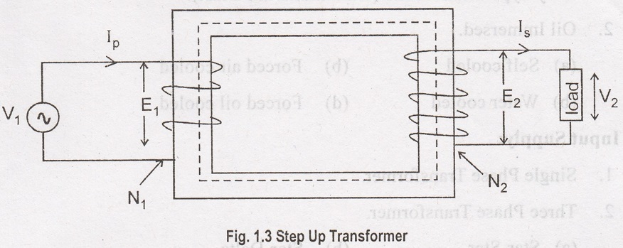
Whenever the primary winding is connected to an a.c source an exciting current flows through the primary winding. Since the current is alternating, it will produce an alternating flux in the core which will be linked by both primary and secondary windings.
WORKING PRINCIPLE OF A TRANSFORMER
Whenever
the primary winding is connected to an a.c source an exciting current flows
through the primary winding. Since the current is alternating, it will produce
an alternating flux in the core which will be linked by both primary and
secondary windings. The induced emf in the primary winding is (E1)
is almost equal to the applied voltage V1 and will oppose the
applied voltage. The emf induced in the secondary winding (E2) used
to deliver power to any load connected across the secondary side of the
transformer.
Thus
power is transferred from the primary to the secondary circuit by mutual
induction. The frequency of induced emf in secondary is same as that of the
supply voltage. The magnitude of the emf induced in the secondary winding will
depends upon its number of turns.
Step Down Transformer: Number of turns in the secondary winding is less than primary winding, shown in Figure 1.2.

Step Up Transformer: Number of turns in the secondary winding is higher than primary winding, shown in Figure 1.3.
Electrical and Instrumentation Engineering: Unit I: Transformer : Tag: Electrical Engineering : - Working Principle of Transformer
Related Topics
Related Subjects

Electrical and Instrumentation Engineering
BE3254 - 2nd Semester - ECE Dept - 2021 Regulation | 2nd Semester ECE Dept 2021 Regulation