Electrical and Instrumentation Engineering: Unit I: Transformer
Transformer Testing
with Solved Example Problems
The circuit constants, efficiency and Voltage regulation of a transformer can be determined by open circuit and short circuit tests. These tests are very convenient as they provide the required information without actually loading the transformer. The Tests are i)Open Circuit or No load test ii)Short Circuit or Impedance test iii)Polarity test iv)Sumpner (or) Back to Back Test
TRANSFORMER TESTING
The circuit
constants, efficiency and Voltage regulation of a transformer can be determined
by open circuit and short circuit tests.
These tests are
very convenient as they provide the required information without actually
loading the transformer.
The power
required to carryout these tests is very small as compared with full load
output of the transformer.
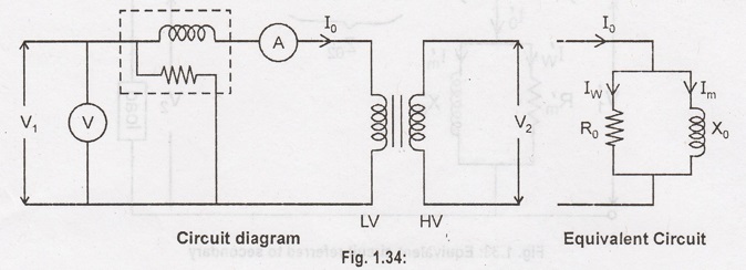
Open Circuit or
No load test
To determine the
iron losses (or core losses (or) fixed losses) and parameters R0 and
X0 of transformer.
The rated
voltage is applied to the primary (usually LV winding) while the secondary is
left open circuited.
The primary
voltage (V1), No load current (I0), No load input power
(W0) are measured.
Normal rated
Voltage is applied to the primary, normal iron losses will occur in the
transformer core. Hence wattmeter will record the iron losses and small copper
loss in the primary.
The No load
current I0 is very small (usually 2-10% of rated current), copper
losses in the primary under no load condition are negligible as compared with
iron losses.
Hence, wattmeter
reading practically gives the iron losses in the transformer. Iron losses are
same at all loads.
Iron losses, P1
= Wattmeter reading (W0)
No load current
= Ammeter reading (I0)
Applied Voltage
= Voltmeter reading (V1)
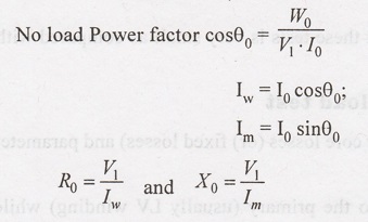
Input Power (W0)
= V1 I0 cos θ0.
In OC test
enables to determine iron losses and parameters R0 and X0
of the transformer.
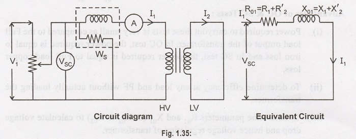
Short Circuit or
Impedance test
This test is
used to determine R01 (or R02), X01 (or X02)
and full load copper losses of the transformer.
In this test,
(usually LV Winding) is short circuited by a thick conductor and variable LV is
applied to the primary.
The LV input is
gradually raised till at voltage VSC, full load current I1,
flows in the primary. Then I2 in the secondary also has FL Valve
since I1 / I2 = N2 / N1
Under these
conditions, the copper loss in the windings is the same as that on FL.
There is no
output from the transformer under short circuit conditions. Therefore, input
power is almost copper loss.
Iron loss is
negligibly small since the voltage VSC is small. Hence the wattmeter
will practically register the full load copper losses in the transformer
winding.
Full load Copper
loss PC = Wattmeter Reading (WS)
Applied Voltage
= Voltmeter reading (VSC)
F.L. Primary
current = Ammeter reading (I1)
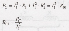
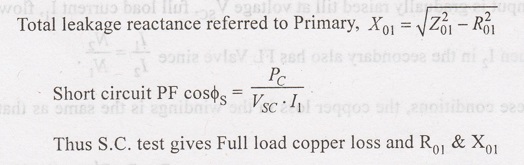
Where R01
- Total resistance of transformer referred to Primary.
Total impedance
referred to Primary, Z01 = VSC / I1
Advantages of OC & SC Tests:
(i) Power
required to carryout these tests is very small as compared to the Full load
output of the transformer. In OC test, the power required is equal to iron loss
and In SC test, the power required is equal to Full load copper loss.
(ii) To
determine efficiency at any load and PF without actually loading the
transformer.
(iii) To
determine parameters R01 and X01(or R02 &
X02) to calculate voltage drop and hence voltage regulation of
transformer.
Example 1.13:
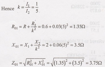
A single phase,
50 Hz transformer has a FL secondary current of 500A, the primary current being
one fifth of this valve. The transformer Parameters are, R1 = 0.6
Ω; R2 =
0.03 Ω; X1
= 2 Ω and X2
= 0.06 Ω. If
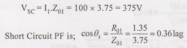
the secondary is short circuited, find the Primary voltage required to
circulate FL current. Neglect the No load current. What is the PF on short
circuit?
Solution :
Neglecting No
load current, the equivalent circuit of transformer on short circuit as
referred to primary is as shown in Fig. 1.36
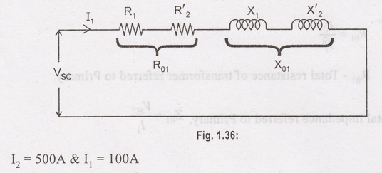
Primary Voltage
required to circulate FL current.
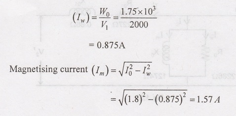
Example 1.14:
A 200 kVA,
2000/440V, 50 Hz, single phase transformer gave the following test results:
O.C. test:
2000V, 1.8A, 1.75 kW on HV side
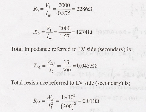
S.C. test: 13V,
300V, 1 kW on LV side
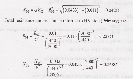
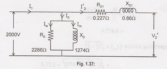
Obtain the
equivalent circuit as referred to HV side.
Solution :
Component of No
load current corresponding to core loss
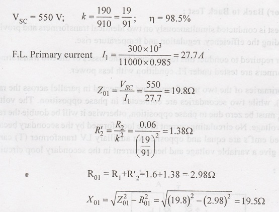
Example 1.15:
The LV winding
of a 300 kW, 11000/2200V, 50 Hz transformer has 190 turns and a resistance of
0.06 Ω. The
HV side has 910 turns and resistance of 1.6 Ω. When LV winding is short circuited, the FL
current is obtained with 550V applied to HV side. Calculate the equivalent
resistance and leakage reactance referred to HV side.
Assume F.L.
efficiency 98.5%
Solution :
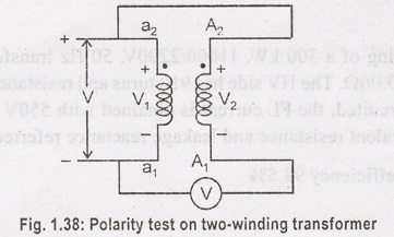
Polarity test:
Polarity test is
used to confirm the correct connection of the line and neutral connections.
Polarity test is must for transformers when parallel operation is done.
In determining
the relative polarity of the two windings of a transformer, the two windings
are connected in series across a voltmeter. One of the windings is excited from
a voltage source. If the polarities of the windings are as marked on the diagram,
the voltmeter reading is V=V1~V2. If the voltmeter reads
(V1+V2), the polarity markings of one of the windings
must be interchanged.
Sumpner (or) Back to Back Test:
This test is
conducted simultaneously on two identical transformers and provides data for
finding the efficiency, regulation and temperature rise.
Power required
to conduct this test is equal to the losses of the two transformers. The
transformers are tested under FL condition with less power.
The primaries of
the two transformers are connected in parallel across the rated supply (V1),
while two secondaries are connected in phase opposition. The voltage across T2T1
must be zero due to phase opposition, otherwise it will be double the rated
secondary voltage. No circulating current in the loop formed by the secondary
because their induced emf's are equal and opposite. An auxillary LV transformer
(T) can be adjusted to give a variable voltage and hence current in the
secondary loop circuit.
Operation:
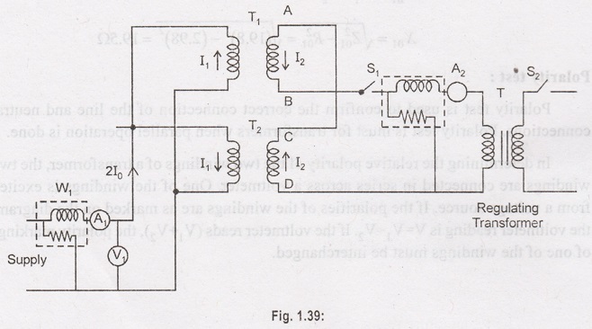
(i) The
secondaries of the transformers are in phase opposition. With switch S1
closed and S2 open, there will be no circulating current (I2=0)
in the secondary loop circuit. Because, the induced emf's in the secondaries
are equal and in opposition. The current drawn from the supply is 2I0
where I0 is the No load current of each transformer. The reading of
W1 equal to the corelosses of the two transformers.
W1 =
Core losses of the two transformers.
(ii) Now switch
(S2) also closed and output voltage of the regulating transformer is
adjusted till Full load current I2 flows in the secondary loop
circuit. The primary current I1 circulates in the primary winding
only and will not pass through W1 (wattmeter 1). The full load
currents are flowing through the primary and secondary winding. Now, the
reading of wattmeter will be equal to the full load copper losses of the two
transformers.
W2 -
Full load copper losses of two transformers.
W1 +
W2 = Total losses of two transformers at FL.
Important Points:
(i) The
Wattmeter (W1) gives the core losses of the two transformers while
wattmeter (W2) gives the FL copper losses (or at any other load
current I2) of the two transformers. Therefore, the power required
to conduct this test is equal to the losses of the two transformers.
(ii) Although
transformers are not supplying any load, yet FL iron-loss and FL Cu losses are
occuring in them.
(iii) There are
two Voltage Sources (Supply Voltage and regulating transformers) and there is
no interference between them. The supply voltage gives only 2I0,
while regulating transformer supplies I2 and hence I1 (-kI2).
Advantages:
1. The power
required to carry out the test is small.
2. Transformers
are tested under FL condition.
3. The iron
losses and FL copper losses are measured simultaneously.
4. I2
can be adjusted to any current value. The cu loss can be found at FL (or) any
load.
5. The
temperature rise can be noted.
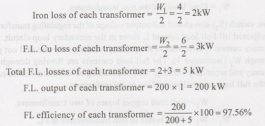
Example 1.16:
In a Back to
Back, the wattmeter W1 reads 4 kW and W2 (at full
current) reads 6 kW. Find the FL efficiency of each transformer. The
transformers are rated at 200 kVA. Assume PF to be unity.
Example 1.17:
Two-similar 250
kVA, 1φ transformers gave the following results when tested by back to back
method.
Mains wattmeter
= 5 kW(W1); Py series circuit wattmeter W2 = 7.5 kW (at
FL current)
(ii) Find the
efficiency of each transformer at 75% FL and 0.8 PF lead.
Solution :
Wattmeter W1
gives the iron losses of the two transformers and W2 gives the FL
copper losses of two transformer
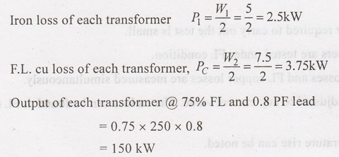
Total losses of
each transformer at 75% full load:
=Pi +
(0.75)2 Pc
= 2.5+ (0.75)2
× 3.75 = 4.61 kW
Input to each transformer
at 75% Full load and 0.8 P.F. lead
= 150 +4.61 =
154.61 kW
Efficiency n of
each transformer is given by:
Separation of No load losses:
The core losses
(or iron losses) consist of hysteresis loss and eddy current loss
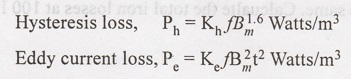
Where,
Bm=
Maximum fluxdensity; f-frequency; Ke, Kh - constants.
For a given
machine maximum flux density (Bm);
Ph
& f and Pe & ƒ2
(or) Ph=
af and Pe = bf2 where 'a' and 'b' are constants.
Total
corelosses, Pi = af + bf2.
Hence if the
total core loss for given Bm is known at two frequencies, the
constants a and b. Can be calculated. Knowing the values of a and b, the
hysteresis loss component and eddy current loss component of the core loss can
be determined.
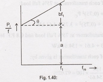
P/f and ƒ curve
= Pi = af + bf2
P/f = a + bf
The total core losses are meausred at various frequencies while the other factors upon which core losses depend are maintained constant. If the graph is plotted between Pi/f and f, it will be a straight line with slope tan φ = b (Fig.1.40). The constants a and b can be evaluated. Hence the hysteresis and eddy current losses at a given can be found out.
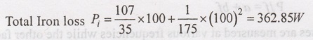
Example 1.18:
The Iron loss in
a certain transformer is 80 kW at 25 Hz and 204 W at 60 Hz. The Maximum flux density
being the same. Calcualte the total iron losses at 100 Hz at the same maximum
flux density.
Solution :
Total iron
losses = (Pi) = af + bf2
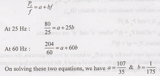
Total iron loss
at 100 Hz can be obtained by putting the values of a, b and f
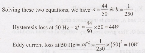
Example 1.19:
The Iron loss in
a transformer core at normal flux density was measured at 30 Hz and 50 Hz. The
results being 30W and 54W. Calculate the hysteresis and eddy current loss at 50
Hz.
Solution :
Total Iron loss
(Pi) = af + bf2
For the first
case; 30 = 30a + b x (30)2
For the second
case; 54 = 50a + b x (50)2
Electrical and Instrumentation Engineering: Unit I: Transformer : Tag: : with Solved Example Problems - Transformer Testing
Related Topics
Related Subjects

Electrical and Instrumentation Engineering
BE3254 - 2nd Semester - ECE Dept - 2021 Regulation | 2nd Semester ECE Dept 2021 Regulation