Electrical and Instrumentation Engineering: Unit I: Transformer
Three Phase Transformer
Working Principle, Construction, Connection Types, Phasor diagram, Advantages, Disadvantages, Applications, Solved Example Problems
Three Phase Transformer Connections are 1. Star-Star (Y-Y) Connection 2. Delta-Delta (A-A) Connection 3. Star-Delta (Y-A) Connection 4. Delta-Star (A-Y) Connection 5. Open-Delta (or) V - V Connection 6. Scott Connection (or) T - T Connection.
THREE PHASE TRANSFORMER
Large scale
generation of electric power is usually 3-phase at generated voltage of 13.2 kV
or somewhat higher. Transmission is generally accomplished at higher voltages
of 110, 132, 275 and 750 kV for that 3 phase transformers are necessary to step
up the generated voltage. Most of the consumer, the distribution voltages are
still reduced to utilization voltages of 440,220 or 110 volts. Here three phase
step down transformer is used. It is economical to use three phase transformer
for transmission and utilization purpose.
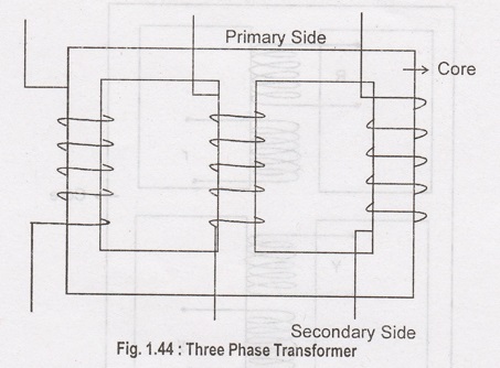
Three phase
transformer construction is similar to single phase transformer as shown in
Figure 1.44. Operation of three phase transformer is similar to single phase
transformer. Three phase supply is given to primary winding. Flux induced in
the core. This flux is linked with secondary winding. Depending upon the Number
of turns in the secondary winding voltage should be stepped up or stepped down.
The connection may be star or delta.
Core Type Three Phase Transformer
Three phase
transformer also categorized as core type and shell type like single phase
transformer.
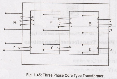
Three phase core
type transformer is shown in Figure 1.45. Magnetic circuits of 3 phases are
interlinked. Each limb carries the fluxes of more than one phase.
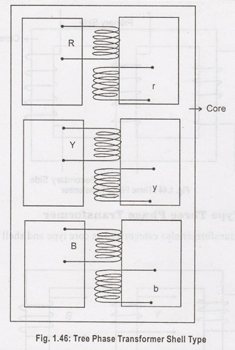
Shell Type Three Phase Transformer
In this type
each limb carries one primary and one secondary winding as shown in Figure 1.46.
Windings are mounted on the central limb. Magnetic circuits of three phases are
more independent than in core type transformer.
Three Phase Transformer Connections
1. Star-Star
(Y-Y) Connection
2. Delta-Delta
(A-A) Connection
3. Star-Delta
(Y-A) Connection
4. Delta-Star
(A-Y) Connection
5. Open-Delta
(or) V - V Connection
6. Scott Connection
(or) T - T Connection.
Star - Star Connection
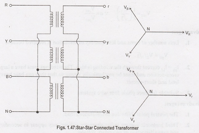
Figure 1.47
shows star-star connection and vector group. This is most economical for small
current rating, high voltage transformers because the phase voltage is 1/√3
times the line voltage.
Number of turns
per phase and quantity of insulation required is minimum. There is a phase
shift of 30° between phase voltage and line voltage on both primary and
secondary where as line voltages in both primary and secondary are in phase
with each other as shown in the phasor diagram. This connection works
satisfactorily only if the load is balanced.
With unbalanced
load to neutral, the neutral points shifts there by making the three line to
neutral voltage unequal.
Ratio of
voltages on the primary and secondary side is equal to the transformation ratio
of each transformer. The star-star connection works well for balanced load. If
the load is unbalanced neutral shifts. To prevent this, star point of the
primary is required to connect to the star point of generator.
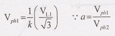
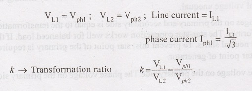
Let VL1,
be the voltage on the primary side. The phase voltage on the primary side is:
Vph1
= VL1 / √3
If 'k' is the
turns ratio, the phase voltage on the secondary is given by:
Advantages:
1. Less number
of turns and less quantity of insulation is required because
Vph =VL
/ √3.
Iph=
IL, current through the winding is high. The windings must have a
large cross-section and must be mechanically strong so that they can bear heavy
load and short-circuit.
3. Suitable for
three phase four wire system.
Disadvantages:
1. The neutral
point shifts due to unbalanced load.
2. Third
harmonic present in the alternator voltage may appear in secondary and cause
distortion of secondary voltage.
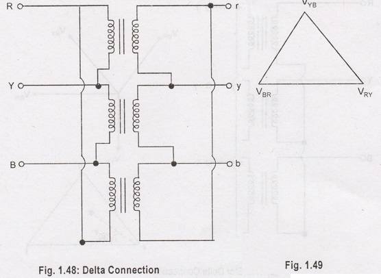
Delta-Delta
Connection (A-A Connection)
This setup is
generally used in systems, which carry large current on low voltages, where
continuity of service must be maintained even though one of the phases develops
fault. Delta-Delta connection shown in Figure 1.48 and 1.49.
VLI →
Line voltage primary
V12 →
Line voltage secondary
Vph1 →
Phase voltage primary
Vph2 →
Phase voltage secondary
Advantages:
1. Output
voltage to be sinusoidal, it is necessary that the magnetizing current of
transformer must contain 3rd harmonic component.
2. During
unbalanced load condition, no neutral shifting.
3. If one
transformer become disabled, the system can continue to operate in open delta
or in V-V at capacity of 58% and not 66.7% of nominal value.
Star-Delta (Y-A)
The main use of
this connection is at the substation end of the transmission line where the
voltage is to be stepped down.
From the phasor
diagram Figure 1.50. 30° phase difference between the primary side and the
secondary allows flow of third harmonics.
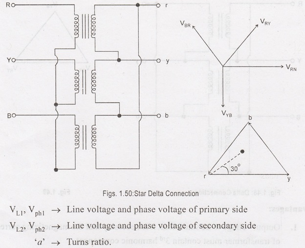
Advantages:
i. Primary is
star connected, few turns are required in primary, which is economical for
power transformers.
ii. To avoid
distortion, primary neutral should be earthed.
iii. Possible to
handle, unbalanced load.
Disadvantages:
i. It is not
possible to make parallel with star-star and delta-delta transformers. Because
secondary voltage is not in phase with primary.
Delta-Star
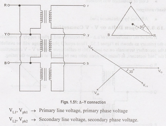
Connection
This connection
is generally employed where it is necessary to step up the voltage. It is used
at the beginning of high tension transmission system. The connection is shown
in Figure 1.51. Neutral of the secondary is grounded for providing 3 phase 4
wire service. It can be used to serve both 3 phase power equipment and single
phase lighting circuits as well. (1φ,3φ loads).
From phasor
diagram it can be seen that there is a 30° phase difference between the primary
and secondary line voltages.
Advantages:
i. 3φ 4 wire
system is possible, since secondary having neutral.
ii. No
distortion due to third harmonics.
iii. Cost of
insulation was reduced.
Disadvantages:
i. Affected by
unbalanced load.
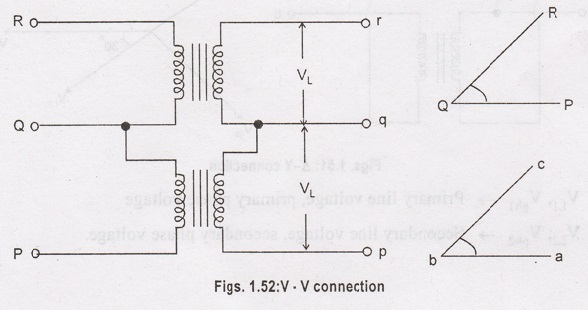
Open Delta or V
- V Connection
If one of the
transformers of a ∆ - ∆ is removed and 3 phase supply is connected to the
primary as shown in Figure 1.52. Three equal 3 phase voltage will be available
at the secondary terminals on no load. This is called open delta or V - V
connections. If the load increases, in future the open delta can be closed to
increase the rating.
The 3 phase load
which can be carried without exceeding the ratings of the transformer is 57.7
per cent of the original load rather than the expected 66.7%. Overload may be
carried temporarily, but some provision must be made to reduce the load if over
heating and consequent break down of the remaining two transformers is to be
avoided.
Disadvantages
1. The average
power factor at which the V bank operates is less than that of the load. This
power factor is actually 86.6% of the balanced load power factor.
2. Secondary
terminal voltages tend to become unbalanced to a great extent when the load is
increased, this happens even when the load is perfectly balanced.
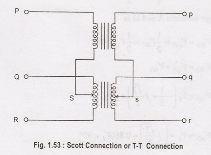
Scott Connection
or T-T Connection
This is another
method of transformation of 3 phase power from one voltage to another by using
two transformers. Charles F Scott proposed it which is shown in Figure 1.53. If
requires two transformers on each side instead of three transformers and
accomplishes three phase to three phase transformations. The transformer which
is a horizontal member of the connection having centre taps both on primary and
secondary is know as the main transformer. The other transformer of primary and
secondary whose one end is connected to the main transformer has a 0.866 tap and
it is called the teaser transformer. Three phase supply is given to the other
end of the teaser and the two ends of the main transformer.
Phasor diagram of Scott Connection Transformer
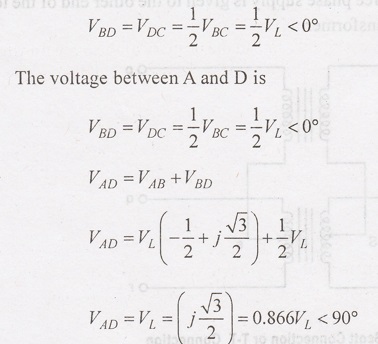
The line
voltages of the 3-phase system VAB, VBC and VCA
which are balanced are shown in the figure 1.54. The same voltage is shown as a
closed equilateral triangle. The figure below shows the primary windings of the
main and the teaser transformer.

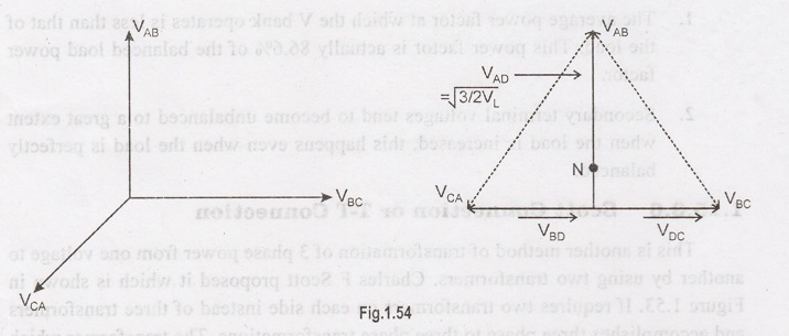
The D divides the
primary BC of the main transformers into two halves and hence the number of
turns in portion BD = the number of turns in portion dC = Tp/2. The
voltage VBD and VDC are equal, and they are in phase with
VBC
The teaser
transformer has the primary voltage rating that is √3/2 or 0.866 of the voltage
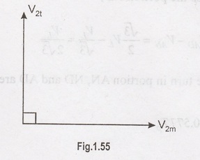
ratings of the main transformer. Voltage VAD is applied to the
primary of the teaser transformer and therefore the secondary of the voltage V2t
of the teaser transformer will lead to the secondary terminal voltage V2m
of the main transformer by 90° as shown in the Figure below.
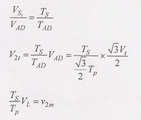
Then, for
keeping the voltage per turn same in the primary of the main transformer and
the primary of the teaser transformer, the number of turns in the primary of
the teaser transformer should be equal to (√3/2) Tp.
Thus, the
secondaries of both transformers should have equal voltage ratings. The V2t
and V2m are equal in magnitude and 90° apart in time; they result in
the balanced 2-phase system.
Position of Neutral Point N
The primary of
the two transformers may have a four wire connection to a 3- phase supply if
the tapping N is provided on the primary of the teaser transformer such that
the voltage across AN = VAN phase voltage = V1 / √3.
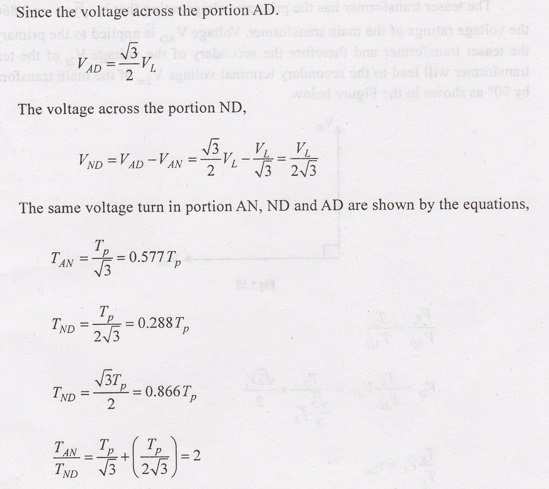
The equation above shows that the neutral point N
divides the primary of the teaser transformer in ration,
AN : ND = 2 : 1
Applications
of Scott Connection
The following are the applications of the Scott-T
connection.
1. The Scott-T connection is used in an electric furnace
installation where it is desired to operate two single-phase together and draw
the balanced load from the three-phase supply.
2. It is used to
supply the single phase loads such as electric train which are so scheduled as
to keep the load on the three phase system as nearly as possible.
3. The Scott-T
connection is used to link a 3-phase system with a two-phase system with the
flow of power in either direction.
The Scott-T
connection permits conversions of a 3-phase system to a two-phase system and vice
versa. But since 2-phase generators are not available, the converters from two
phases to three phases are not used in practice.
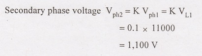
Example 1.20:
A 3 phase
transformer is used to step down the voltage of a 3 phase, 11 kV feeder line,
per phase turn ratio is 10. For a primary line current of 25 A. Calculate the
secondary line voltage, line current and kVA for the following connections. (i)
Star-Delta (ii) Delta-Star.
Solution:
(a) Star-Delta

(a) Delta - Star

APPLICATIONS OF THREE PHASE TRANSFORMER
i. Power Station Generator
ii. Machine Transformer
iii. Network
Transformer
iv. Distribution
Transformer
v. Substation
Transformer
Electrical and Instrumentation Engineering: Unit I: Transformer : Tag: : Working Principle, Construction, Connection Types, Phasor diagram, Advantages, Disadvantages, Applications, Solved Example Problems - Three Phase Transformer
Related Topics
Related Subjects

Electrical and Instrumentation Engineering
BE3254 - 2nd Semester - ECE Dept - 2021 Regulation | 2nd Semester ECE Dept 2021 Regulation