Electrical and Instrumentation Engineering: Unit I: Transformer
Equivalent Circuit of a Transformer
Equivalent circuit of transformer is resolved into an equivalent circuit in which the resistance and leakage reactance of the transformer are imagined to be external to the winding which transform the voltage.
EQUIVALENT CIRCUIT OF A TRANSFORMER
Equivalent
circuit of transformer is shown in Figure 1.29. It is resolved into an
equivalent circuit in which the resistance and leakage reactance of the
transformer are imagined to be external to the winding which transform the
voltage.

At no load condition,
the primary of a transformer draws no load current I0. It is mainly
used to supply the iron loss and to produce the flux in the core. Iron loss is
represented by Rm and the magnetizing current is Xm. Rm
and Xm are connected in parallel to primary winding. It is called as
no load branch (or) exciting branch. (Rm and Xm).
R1 - Primary
winding resistance in Ω
X1 - Primary
winding reactance in Ω
Rm - No
load resistance in Ω
Xm - No
load reactance in Ω
I1 - Full
load primary current in Amps
I0 -
No load primary current in Amps
I2'-Load
component of primary current in Amps
Iw - Working
component
Im - Magnetizing
component
E1 - Induced
emf in primary winding in Volts
E2 - Induced
emf in secondary winding in Volts
R2, X2
- Secondary winding resistance in Q, secondary winding reactance in Ω
I2 - Full
load secondary current in A
k - Transformation
Ratio.
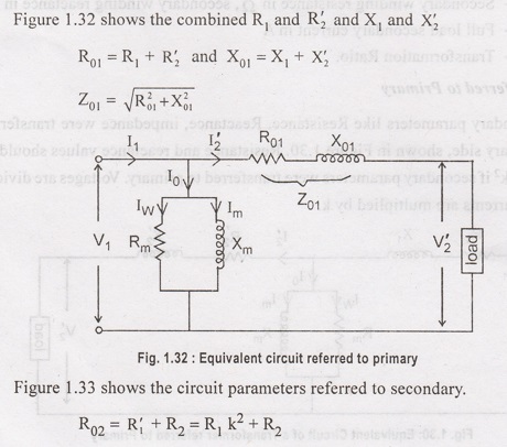
Circuit Referred to Primary
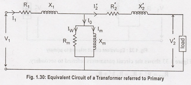
Secondary parameters like Resistance, Reactance, impedance were transferred to the primary side, shown in Figure 1.30. Resistance and reactance values should be divided by k2 if secondary parameters were transferred to primary. Voltages are divided by k and currents are multiplied by k.

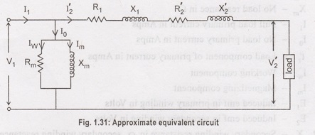
Approximate equivalent circuit:
The no-load
current I is only 1-3% of rated primary current. So I2' is
practically equal to I1. Due to this, the equivalent circuit can be
simplified by transferring the exciting branch (Rm and Xm)
to the left position of the circuit shown in Figure 1.31.
Electrical and Instrumentation Engineering: Unit I: Transformer : Tag: : - Equivalent Circuit of a Transformer
Related Topics
Related Subjects

Electrical and Instrumentation Engineering
BE3254 - 2nd Semester - ECE Dept - 2021 Regulation | 2nd Semester ECE Dept 2021 Regulation