Electrical and Instrumentation Engineering: Unit I: Transformer
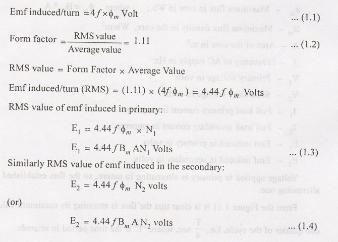
EMF Equation of a Transformer
Derivation
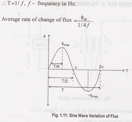
Voltage applied to primary is alternating in nature, so the flux established also alternating one.
EMF EQUATION OF A TRANSFORMER
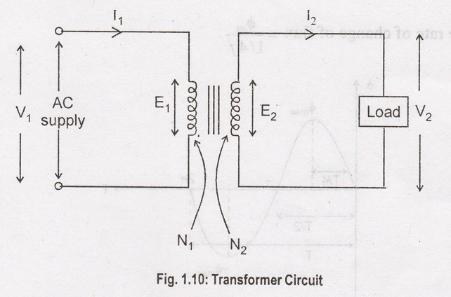
Assume a
transformer arrangement as shown in Figure 1.10:
N1 -
No. of turns in primary winding
N2 -
No. of turns in secondary winding
Φm -
Maximum flux in core in Wb.; where φm = Bm*A
Bm -
Maximum flux density in the core, Wb/m2
A - Area of the
core in m2
f - Frequency of
AC supply in Hz
V1 -
Primary voltage in volts
V2 -
Secondary voltage in volts
I1 -
Full load primary current in amperes
I2 -
Full load secondary current in amperes
E1 -
Emf induced in primary in volts
E2 -
Emf induced in secondary in volts
Voltage applied
to primary is alternating in nature, so the flux established also alternating
one.
From the Figure
1.11 it is clear that the flux is attaining its maximum value in one quarter of
the cycle. i.e., T/4 sec. where 'T' is the time period in seconds.
If we assume
single turn coil, then according to Faraday's laws of electromagnetic
induction,
Electrical and Instrumentation Engineering: Unit I: Transformer : Tag: : Derivation - EMF Equation of a Transformer
Related Topics
Related Subjects

Electrical and Instrumentation Engineering
BE3254 - 2nd Semester - ECE Dept - 2021 Regulation | 2nd Semester ECE Dept 2021 Regulation