Electrical and Instrumentation Engineering: Unit I: Transformer
Construction of Transformer
Components, Working Principle
Main Components of Transformers are: i. Magnetic Core, ii. Windings, iii. Insulation for Windings, iv. Conservator (or) Tank, v. Cooling arrangement, Temperature Gauge, Oil Gauge, vi. Buchholz relay, vii. Silica gel breather, viii. Bushings (either of porcelain, oil-filled or capacitor type).
TRANSFORMER CONSTRUCTION
Main
Components of Transformers are:
i.
Magnetic Core
ii.
Windings (Primary and Secondary)
iii.
Insulation for Windings
iv.
Conservator (or) Tank
v.
Cooling arrangement, Temperature Gauge, Oil Gauge
vi.
Buchholz relay
vii.
Silica gel breather
viii.
Bushings (either of porcelain, oil-filled or capacitor type).
Magnetic
Core
In
all types of transformers, the core is constructed of transformer sheet steel
laminations assembled to provide a continuous magnetic path with a minimum of
air- gap included, the steel used is of high silicon content, sometimes heat
treated to produce a high permeability and a low hysteresis loss at the usual
operating flux densities.
Eddy
current loss is minimized by laminating the core the laminations being
insulated from each other by a high coat of core-plate varnish or by an oxide
layer on the surface. The thickness of laminations varies from 0.35 mm for a
frequency of 50 Hz to 0.5 mm for a frequency of 25 Hz. The joints in the
alternate layers are stragged in order to avoid the presence of narrow gaps
right through the cross-section of the core. Such staggered joints are said to
be 'imbricated'.
Constructionally,
the transformers are of two types, differentiated from each other by the manner
in which the primary and secondary coils are placed around the laminated core.
They are:
i.
Core Type
ii.
Shell Type.
In
Core Type transformers winding surround the core or shell. (i.e) it is wounded
considerable part of the core.
In
Shell Type transformers the core (or) shell surrounds a considerable portion of
the windings.
Another
recent development is spiral-core or wound-core type. All transformers are
shown in Figure 1.4.

Windings
There
are two windings in a transformer. They are called primary and secondary
windings. Windings are made of copper shown in Figure 1.5.

Insulation
for Windings
Paper
is used as insulating material widely. Enamel insulation is used as the
inter-turn insulation of low voltage transformers. For power transformers
enameled copper with paper insulation is also used. Some of the insulation
materials are shown in Figure 1.5 and 1.6. Example: paper, oil, varnish,
oxides.
Conservators
or Expansion Tank
A
small auxiliary oil tank may be mounted above the transformer and connected to
main tank by a pipe. Main function of the conservator is to maintain oil level
in the transformer even though the coil may expands or contracts with the change
in temperature. A pipe connection between the gas space in the expansion tank,
and the cover of the transformer to pass into the expansion tank, so that the
transformer tank will be completely filled with oil. Conservator/Expansion tank
is shown in Figure 1.6.

Cooling
Arrangements, Temperature Gauge, Oil Gauge
The
various methods of cooling employed in a transformer are:
(i) Oil Immersed Natural Cooled
Transformers: The coil and core are immersed in
insulating oil contained in an iron tank. The heat produced in the shell and
windings is transferred or removed by the circulation of oil to the surface
which dissipates heat to surroundings. If the size of the transformer is big
then No. of tubes used were increased. It is not only for keeping the windings
cool but also provides additional insulation some of the cooling systems are
shown in Figure 1.7.
(ii) Oil Immersed Forced Air Cooled
Transformer: This type also core and windings are immersed
in oil and cooling is increased by forced air over the cooling surfaces like
tank, tubes and radiators by means of far mounted externally to the
transformer.
(iii) Oil Immersed Water Cooled
Transformer: Same as previous cooling system,
additionally cold water will circulate through the tubes immersed in oil. It
will collects the heat from the oil.
(iv) Oil Immersed Forced Oil Cooled
Transformer: As name indicate core and windings are
immersed in oil and oil is forced to flow through the tubes with the help of
centrifugal pump located at the inlet/outlet.
(v) Air Blast Cooling:
Here the transformers is cooled by a forced circulation of air through core and
windings. It is used in substations located in dusty place where oil is
considered as a fire hazard. Filters are used to avoid the entry of dust into
the ducts.
Temperature
gauge is used to indicate the oil temperature which is shown in Figure 1.7 and
hottest spot temperature. It is also having alarm unit which is used alert the
worker, if the temperature violates the limit.
Likewise,
oil gauge is used to indicate the oil level of the transformer. Alarm circuit
gives an alarm when the oil level has dropped beyond permissible height due to
oil leak or due to any other reason.

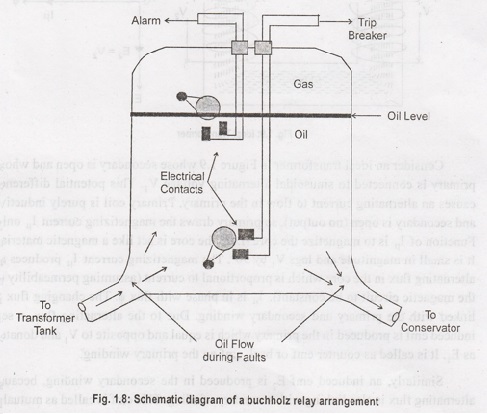
Buchholz
Relay
Buchholz
Relay in transformer is an oil container housed the connecting pipe from main
tank to conservator tank. It has mainly two elements. The upper element consist
of a float. The float is attached to a hinge in such a way that it can move up
and down depending on the oil level. One mercury switch is fixed on the float.
The alignment of mercury switch hence depends upon the position of the float.
The
lower element consist of a baffle plate and mercury switch. This plate is
fitted on a hinge first in front of the inlet (main tank side) of Buchholz
relay in transformer in such a way that when oil enters in the relay from that
inlet in high pressure the alignment of the baffle plate along with the mercury
switch attached to it, will change.
Working:
It
is based on mechanical phenomenons and is mechanically actuated shown in Figure
1.8. Whenever there will be a minor internal fault in the transformer such as
an insulation faults between turns, break down of core of transformer, core
heating, the transformer insulation oil will be decomposed in different
hydrocabron gases, Co2 and Co. The gas produced due to decomposition
of transformer insulating oil will accumulate in the upper part, and the Buchholz
container which causes fall of oil level in it.
When
transformer is with load, the temperature of the transformer insulating oil
increases, consequently the volume of the oil is increased. As the volume of
the oil is increased, the air above the oil level in conservator will come out.
Again at low oil temperature, the volume of the oil is then decreased, which
causes the volume of the oil to be decreased which again causes air to entire
into conservator tank.
Air
always consist of moisture and it is mixed up with oil if it is allowed to
enter into the transformer. Moisture should be resisted or prevented during the
entry of air into the transformer, because moisture is harmful for transformer
insulation. A silica gel breather is the most commonly used way of filtering
moisture from air.
Silical
gel crystal has tremendous capacity of absorbing moisture. When air passes
through these crystals in the breather and moisture is absorbed by them.
Bushing
is an insulated device that allows an electrical conductor to pass safely
through an (usually) earthed conducting barrier wall of a transformer. This
bushing is made up of porcelain material with capacitors placed around the
wire.
Electrical and Instrumentation Engineering: Unit I: Transformer : Tag: : Components, Working Principle - Construction of Transformer
Related Topics
Related Subjects

Electrical and Instrumentation Engineering
BE3254 - 2nd Semester - ECE Dept - 2021 Regulation | 2nd Semester ECE Dept 2021 Regulation