Electrical and Instrumentation Engineering: Unit I: Transformer
Auto Transformer
Equivalent Circuit, Working Principle, Uses, Advantages, Disadvantages
Auto transformer is a transformer with one winding, in which part of winding is common to both primary and secondary. Primary and secondary are not electrically isolated from each other as in case with a 2 winding transformer.
AUTO TRANSFORMER
It is a
transformer with one winding, in which part of winding is common to both
primary and secondary. Primary and secondary are not electrically isolated from
each other as in case with a 2 winding transformer. But its theory and
operation are similar to those of a two-winding transformer. Because of one
winding, it uses less copper and hence is cheaper. It is used where
transformation ratio differs from unity. Figure 1.56(a) and 1.56(b) shows step
down and step-up auto transformer.
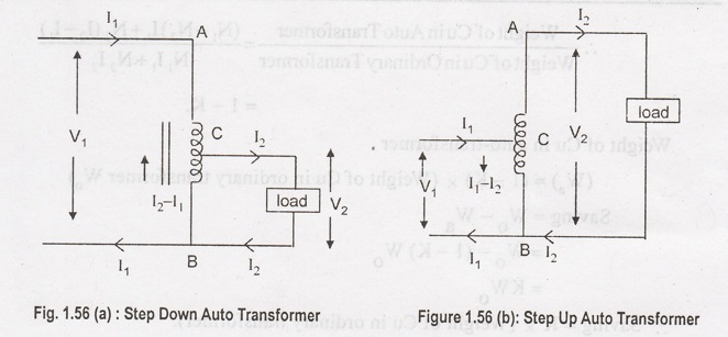
Figure 1.54(a)
AB is primary winding having N, turns and BC is secondary winding having N2
turns. Neglecting iron losses and no-load current.
V2 / V1
= N2 / N1 = I1 / I2 = K
The current in
section CB is difference of I1 and I2. But as the two
currents are practically in phase opposition, the resultant current is (I2
– I1). (i.e) I2 >I1. As compared to an
ordinary 2-winding transformer of same output, an auto transformer has higher
efficiency but smaller size. Its voltage regulation is much better.
Saving of Cu: Volume and weight of cu, is
proportional to the length and area of the cross section of the conductors. Now
length of conductor is proportional to the number of turns and cross section
depends on current. Weight is proportional to the product of the current and
number of terms.
Weight of Cu in
section AC is α (N1 - N2) I1;
Weight of Cu in
section BC is α N2 (I2 − I1).
Total weight of
Cu in Auto-transformer α (N1 - N2) I1 + N2
(I2 – I1).
If a two-winding
transformer were to perform the same duty, then weight of Cu on its primary α N1I1
; ωt of Cu on secondary α N2I2.
Total weight of Cu
α N1I1 + N2I2

Hence, saving
will increase as K approaches unity. It can be proved that power transformed
inductively input (1 - K). The rest of the power = (K × input) is conducted
directly from the source to the load. i.e., It is transferred conductivity to
the load.
Uses:
1. To give small
boost to a distribution cable to correct the voltage drop.
2. As
auto-starter transformers to give upto 50 to 60% of full voltage to an induction
being motor during starting.
3. As furnace
transformers for getting a convenient supply to suit the furnace winding from a
230 V supply.
4.
Interconnecting transformers in 132 kV/330 kV system.
5. In control
equipment for 1-phase and 3-phase electrical locomotives.
Advantages of using Auto Transformer
1. For
transformation ratio = 2, the size of the auto transformer would be
approximately 50% of the corresponding size of two winding transformer. For
transformation ratio say 20 however the size would be 95%. The saving in cost
of the material is of course not in the same proportion. The saving of cost is
appreciable when the ratio of transformer is low, that is lower than 2. Thus
auto transformer is smaller in size and cheaper.
2. An auto
transformer has higher efficiency than two winding transformer. This is because
of less ohmic loss and core loss due to reduction of transformer material.
3. Auto
transformer has better voltage regulation as voltage drop in resistance and
reactance of the single winding is less.
Disadvantages of using Auto Transformer
1. Because of
electrical conductivity of the primary and secondary windings the bar lower
voltage circuit is liable to be impressed upon by higher voltage. To avoid breakdown
in the lower voltage circuit, it becomes necessary to design the low voltage
circuit to withstand higher voltage.
2. The leakage
flux between the primary and secondary windings is small and hence the
impedance is low. This results into severer short circuit currents under fault
conditions.
3. The
connections on primary and secondary sides have necessarily needs to be same,
except when using interconnected starring connections. This introduces complications
due to changing primary and secondary phase angle particularly in the case of
delta/ delta connection.
4. Because of
common neutral in a star/star connected auto transformer it is not possible to
earth neutral of one side only. Both their sides should have their neutrality
either earth or isolated.
5. It is more
difficult to maintain the electromagnetic balance of the winding when voltage
adjustment tappings are provided. It should be known that the provision of
tapping on an auto transformer increases considerably the frame size of the
transformer. If the range of tapping is very large, the advantages gained in
initial cost is lost to a greatevent.
Three Phase
transformers are widely used as Power transformers, Distribution transformers
and in Electrical Grids.
1. When we
generate the Power using an alternator(AC), the voltage at which it is
generated is of mostly 11KV( Sometimes a bit more than that but not too high
due to insulation constraints). For transmitting purpose we install a
transformer just after the generator so that it can step up/down tge voltage).
Moreover, it is better to generate in 3 phase rather than 1 phase due to many
advantages. Therefore, the transformer you have to use should be a 3 phase one.
2. Some loads
such as industrial, and commercial require 3 phase transformers to meet their
demand.
3. The transmission voltage such as 132/220 KV, we need step up/down in the both ends of Transmission lines. There are lots of applications of 3 phase transformers, I am just giving an idea of its major application. Hope it'll help you.
Electrical and Instrumentation Engineering: Unit I: Transformer : Tag: : Equivalent Circuit, Working Principle, Uses, Advantages, Disadvantages - Auto Transformer
Related Topics
Related Subjects

Electrical and Instrumentation Engineering
BE3254 - 2nd Semester - ECE Dept - 2021 Regulation | 2nd Semester ECE Dept 2021 Regulation