Electrical and Instrumentation Engineering: Unit I: Transformer
Accounting for Finite Permeability and Core Loss
Transformer On Load and No Load with Solved Example Problems
We will consider two cases: (i) when a transformer is on no load, (ii) when it is loaded.
ACCOUNTING FOR FINITE PERMEABILITY AND CORE LOSS
We will consider
two cases:
(i) when a
transformer is on no load,
(ii) when it is
loaded.
Transformer on
No-Load
In above
discussion, we assumed an ideal transformer (i.e.,) one in which there were no
core losses and copper losses. When an actual transformer is put on load, there
is iron loss in the core and copper loss in the windings (both primary and
secondary) and these losses are not entirely negligible.
When the
transformer is on no load, the primary input current is not wholly reactive.
The primary input current under no-load condition has to supply:
i. iron losses
in the core (i.e.,) hysteresis loss and eddy current loss.
ii. A very
small amount of copper loss in primary (there being no cu loss in secondary as
it is open). Hence, the no-load primary input current I0 is not at
90° behind V1 but logs it by an angle φ0 angle 90°. No
load input power
W0 =
V1 I0 cos φ0
cos φ0
- Primary power factor under no load condition. Its vector diagram is shown in
Figure 1.12.

Primary currents I0 has two components:
i. Iω
is in phase with V1. This is known as active or working (or) iron
loss component Iω because it mainly supplies the iron loss plus small
quantity of primary Cu loss.
Iω =
I0 cos φ0
ii. The other component
is in quadrature with V1 and is known as magnetizing component Iµ
because its function is to sustain the alternating flux in the core. It is
wattless.
Iµ =
I0 sin φ0
I0 is
the vector sum of Iω and Iµ
I0 =
(Iµ2 + Iω2)
Some of Points to be Noted:
1. The no load
primary current I0 is very small as compared to the full load
primary current. It is about 1 per cent of the full load current.
2. Owing to the
fact that the permeability of the core varies with the instantaneous To som
value of the exciting current, the wave of the exciting or magnetizing current
is the wave not truly sinusoidal. It should not be represented by a vector
because only sinusoidally varying quantities are represented by rotating
vectors. But in practice, it makes no appreciable difference.
3. As I0
is very small, the no load primary cu loss is negligibly small which means that
no load primary input is practically equal to the iron loss in the transformer.
4. The core-loss
which is responsible for shift in the current vector, angle φ0 is
known as hysteresis angle of advance.
Example 1.7:
(a) A 2,200/200
V transformer draws a no-load primary current of 0.6 A and absorbs 400 Watts.
Find the magnetizing and iron loss current.
(b) A 2,200/250
V transformer takes 0.5 A at a p.f of 0.3 on open circuit. Find magnetizing and
working components of no load primary current.
Solution:

Example 1.8:
A single phase
transformer has 500 turns on the primary and 40 turns on the secondary winding.
The mean length of the magnetic path in the iron core is 150 cm and the joints
are equivalent to an air gap of 0.1 mm. When a potential difference of 3000 V
is applied to the primary. Maximum flux density is 1.2 Wb/m2.
Calculate (a) the cross sectional area of the core, (b) no load secondary
voltage, (c) the no load current drawn the primary, (d) power factor on no load.
Given that AT/cm for a flux density of 1.2 Wb/m2 in iron to be 5,
the corresponding loss to be 2 watt/kg at 50 Hz and the density of iron as 7.8
gram/cm3.
Solution:
E1 =
4.44 f Bm A
3000 = 4.44 × 50
× 1.2 × A
A = 3000/4.44 ×
50 × 1.2 = 0.0225 m2
A = 225 cm2.
This is the net
cross-sectional area. However, the gross area would be about 10% more to allow
for the insulation between laminations.
(b) k = N2
/ N1 = 40/500 = 4/50
No load
secondary voltage = KE1 = (4/50) × 3000 = 240V.
(c) AT per cm =
5: AT for iron core = 150 × 5 =750
AT for air gap =
Hl = (B/ µ0) ×
l = (1.2/4п ×10-7)
×0.0001 = 95.5
Total AT Bmax
= 750 + 95.5 = 845.5.
Maximum value of
magnetizing current drawn by primary = 845.5/500 = 1.691 A
Assuming this
current to be sinusoidal, its rms value is Iµ = 1.691/√2 = 1.196 A
Volume of iron =
length × Area = 150 × 225 = 33,750 cm3
Density = 7.8
gram/cm3
Mass of iron =
33,750 × 7.8/1000 = 263.25 kg
Total iron loss
= 263.25 × 2 = 526.5 W.
Iron loss
component of no load primary current I0 is:

Transformer on
Load
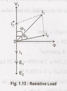
When the
secondary winding is connected to a load, then transformer is said to be on load
as shown in Figure 1.13. I2 current will flow through the load, when
the transformer is connected to load. The magnitude and phase of I2
with respect to V2 is determined by the characteristics of the load.
Current I2
is in phase with V2 if load is resistive. If it is inductive load, I2
lags V2. If I2 leads V2 then it is the
response of capacitive load. At no load condition No load current I0
will flow through primary winding of transformer which is shown in figure and I0
setup the flux φ.
Under loaded
condition, secondary current I2 produces the φ2 which is
in opposition to the main primary flux φ which is produced due to I0.
The secondary ampere turns are called as demagnetizing ampere-turns. The
opposing flux φ2 weakness the primary flux φ momentarily, so that
back emf E1 is reduced. For a moment V1 gains the upper
hand over E1 and hence causes more current (I2) to flow
in primary. It is called as load components of primary current. It is
opposition with I2. Hence φ2' and φ2 cancels
each other shown in Figure 1.13 and 1.14.

Hence, whatever
the load conditions, the net flux passing through the core is approximately the
same as at no load. Due to constancy of core flux at all loads, the core loss
is also practically the same under all load condition.
φ2 = φ2'
N2 I2
= N1 I2'
I2' =
(N2/N1) × I2
I2' =
k I2.
When the
transformer is on load, the primary winding has two current in it. The total
primary current is the vector sum of I0 and I2'
In Figure 1.14
show the vector diagrams for a loaded transformer when load is non-inductive
and for inductive, I0 Figure 1.14. I2 is secondary
current in phase with E2 (i.e., V2). It causes primary
current I2' which is anti-phase with it and equal to it in magnitude
(k = 1). Total primary current is the vector sum of I0 and I2'
and lags behind V1 by an angle φ.
In Figure
1.14(b) vectors are drawn for inductive load. Here I2 lags E2
(i.e., V2) by φ2. Current I2' is again
antiphase with I2 and equal to it in magnitude. As before, I1
is the vector sum of I2' and I0 and lags behind V1
by φ1
N2/N1
= I2'/I2 = I1/I2 = k
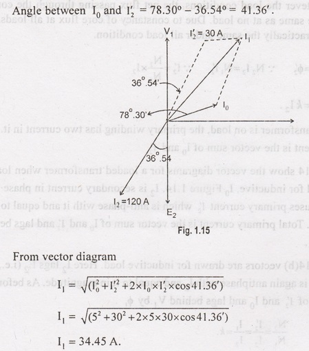
Example 1.9:
A single phase
transformer with a ratio of 440/110 V takes a no-load current of 5A and 0.2
power factor lagging. If the secondary supplies a current of 120 A at a p.f of
0.8 lagging. Estimate the current taken by the primary.
Solution:
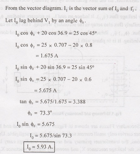
Example 1.10:
A transformer
has a primary winding of 800 turns and a secondary windings of 200 turns. When
the load current on the secondary is 80 A at 0.8 power factor lagging. The
primary current is 25 A at 0.707 power factor lagging. Determine the no load
current of the transformer and its phase with respect to the voltage.
Solution:


Transformer
Winding Resistance and Reactance
In practical
transformer, the windings having some resistance. The primary winding has
primary resistance. It is called as R1, R2 is the
secondary resistance of secondary winding.

In practical
transformer, all the flux generated by the primary does not link the secondary
winding. Some flux passes through air instead of flowing through the core. This
called primary leakage flux (φL1). It induce an emf L1 in
primary winding. φL1 is in phase with I1. Similarly flux
also setup in the secondary winding. This flux is called secondary leakage
flux. (φL2). φL2 induces the emf eL2 in
secondary winding and doesnot links the primary winding. It is in phase with I2.

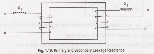
Primary and
Secondary Fluxes are shown in Figure 1.18. At no load and light loads, the
transformer carries only small current so leakage fluxes are negligible. Under
heavy load conditions, the transformer primary and secondary windings carry
large currents. Due to this, the leakage reactance X1 and secondary
leakage reactance X2 are shown in Figure 1.19.
The practical
transformer should have winding resistances and leakage reactance i.e., R1,
R2, X1 and X2. It is shown in Figure 1.20

Electrical and Instrumentation Engineering: Unit I: Transformer : Tag: : Transformer On Load and No Load with Solved Example Problems - Accounting for Finite Permeability and Core Loss
Related Topics
Related Subjects

Electrical and Instrumentation Engineering
BE3254 - 2nd Semester - ECE Dept - 2021 Regulation | 2nd Semester ECE Dept 2021 Regulation