Electronic Devices and Circuits: Unit II: Amplifiers
Important Problems in Amplifiers
Anna University Important Solved Problems
SOLVED PROBLEMS
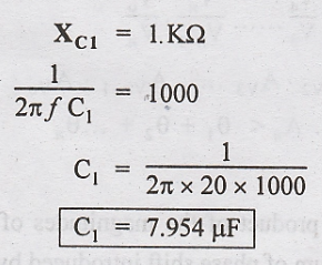
Problem 2.1
An
audio frequency amplifier is to be designed for operating over a range of 20 HZ
and 20 KHz. Calculate the value of input coupling capacitor C1 if
the total series resistance is 10 KΩ
Given:

To Find:
Coupling
Capacitor C1
Solution:
Problem 2.2
For a typical voltage amplifier, the voltage gain = 100 at the cut-off frequencies. Find the maximum voltage gain.
Given:
Voltage
gain = 100
To Find:
Maximum
voltage gain
Solution:

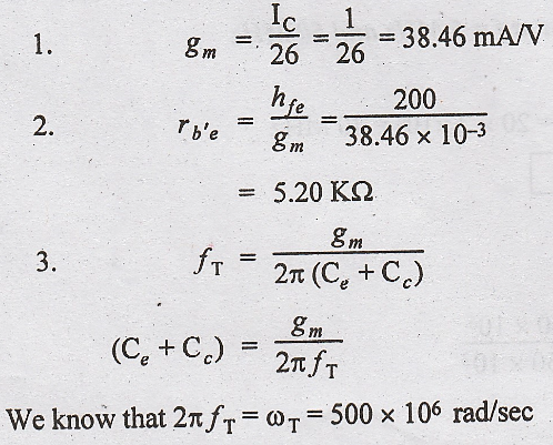
Problem 2.3
At
IC = 1 mA and VCE = 10 V, a transistor have Cc
= Cb'c = 3 pF, hfe = 200 and ωT = 500 µ
rad/sec. Calculate gm, rb'e, Ce and ωβ.
Given:

To find:
gm,
rb'e, Ce, ωβ.
Solution:

Problem 2.4
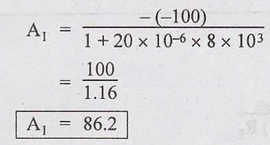
The
short circuit CE gain of a transistor at 2 MHz is 20. The value of fB
is 150 KHz. Calculate 1.fT 2. hfe 3. Current gain at f =
5 MHz and 50 MHz.
Given:
f
= 2 MHz
A1
= 20
fB
= 150 KHz
To find:

Solution


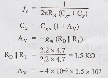
Problem 2.5
For
the FET amplifier, the component values are RD= 2.2 KΩ RL
= 4.7 ΚΩ, RG = 10 ΜΩ RS = 600 Ω, Cgd = 2 pF, Cgs
= 4 pF, gm = 4 mS. Determine the high frequency response of this
amplifier.
Given:

To Find:
Frequency
response of amplifier
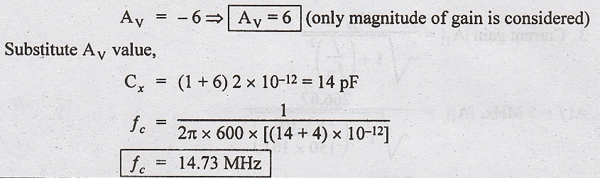
Solution:
Cut
off frequency of the input RC network
Problem 2.6
A
CE amplifier is driven by a voltage source of internal resistance RS
= 800 Ω and the load impedance is a resistance RL = 1000 Ω The
h-parameters are hie = 1 KΩ, hre = 2 × 10⁻⁴, hfe
= 50, hoe = 25 μA/V. Compute the current gain A1, input
impedance Ri, voltage gain AV and output impedance Ro.
Solution:

Problem 2.7
A
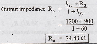
voltage source of internal resistance RS = 900 Ω drives a CC
amplifier using load resistance RL = 2000Ω. The CE h-parameters are
hie = 1200 Ω, hre = 2 x10⁻⁴, hfe =
60 and hoe = 25 μA/V. Compute the current gain, input impedance,
voltage gain and output impedance.
Solution:
Current
gain, A1 = 1 + hfe = 1 + 60 = 61
Input
impedance,


Problem 2.8
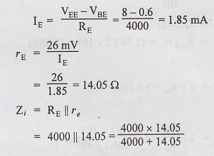
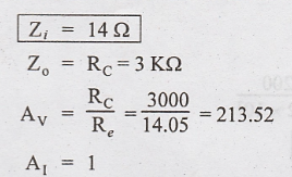
Find
the input impedance, output impedance, voltage gain and current gain for the CB
circuit shown in Fig.2.35. Assume VBE = 0.6 V

Solution
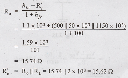
Problem 2.9
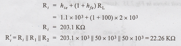
An
emitter follower has circuit parameter RS = 500Ω, R1 = R2
= 50 KΩ, RL = 2 KΩ, hfe = 100, hie = 1.1 KΩ
Determine the input impedance, output impedance, ΚΩ, current gain and voltage
gain.
Solution:
1.
Input Impedance
2.
Output Impedance
3.
Current Gain

4.
Voltage Gain
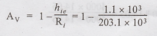
AV
= 0.9946
Problem 2.10
The
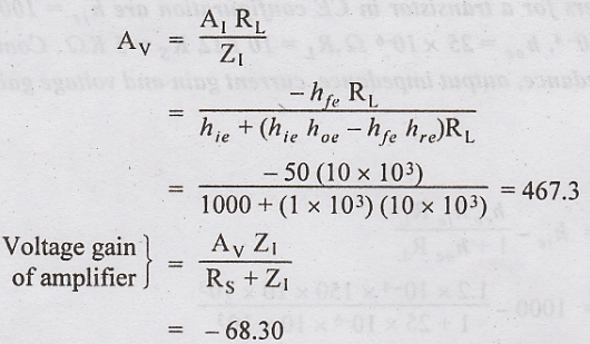
hybrid parameters for a transistor in CE configuration are hie =
1000 Ω, hfe = 150, hre = 1.2 x 10⁻⁴, hoe
= 25 x 10-6 Ω, RL= 10 KΩ, RS = 5 KΩ. Compute the values
of input impedance, output impedance, current gain and voltage gain.
Solution:
1.
Input Impedance

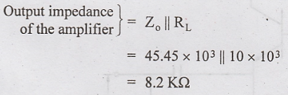
2.
Output Impedance

3.
Current Gain

4.
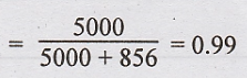
Voltage Gain
Problem 2.11
The
common collector amplifier shown in Fig.2.36 has VCC = 10 V, RB
= 470 KΩ, RE = 3.3 KΩ, β is 100. Find the input impedance of the
amplifier and overall voltage gain.

Solution:
From
Fig.2.36,


Problem 2.12
Calculate
the current gain, voltage gain, input and output impedance for the CC amplifier
shown in Fig.2.37, hic = 1.4 KΩ, hfe = 100, hrc
= 20 µA/V, hoc = 20 × 10-6.
Solution:
Current
gain

Input
Impedance


Voltage
gain

Output
Impedance


Electronic Devices and Circuits: Unit II: Amplifiers : Tag: : - Important Problems in Amplifiers
Related Topics
Related Subjects

Electronic Devices and Circuits
EC3353 - EDC - 3rd Semester - ECE Dept - 2021 Regulation | 3rd Semester ECE Dept 2021 Regulation