Physics for Electronics Engineering: Unit IV: Optical Properties of Materials
Excitonic State & Organic Light Emitting Diode (OLED)
Construction, Working Principle, Band Structure diagram, Advantages, Drawbacks, Applications
The two bands are separated by the bandgap. The Organic semiconductor materials have HOMO and LUMO bands like valence and conduction bands in inorganic semiconductors (Si, Ge, GAs etc). This gives a "single-electron energy-momentum" relation
EXCITONIC STATE
The
two bands are separated by the bandgap. The Organic semiconductor materials
have HOMO and LUMO bands like valence and conduction bands in inorganic semiconductors
(Si, Ge, GAs etc). This gives a "single-electron energy-momentum"
relation as shown in Fig. 4.27 (a).
Consider
an electron being removed from the valence band and excited to a higher energy
state. The lowest energy needed to excite the system is the bandgap energy Eg.
The electron and hole interact with each other (since the hole responds like a positively charged particle) as shown in fig. 4.27 (b). The bound state of electron-hole system is called excition and it can be represented by the hydrogen-like model.
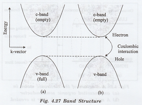
The
exciton energy is slightly lower than the bandgap energy of the semiconductor.
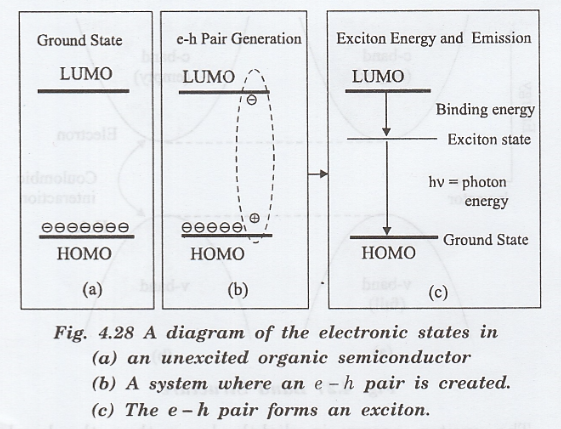
Excitonic states can be observed absorption spectra and and are used for
many electronic devices
In the organic semiconductors the molecular
nature of the electronic state causes the electron-hole state to be tightly
localized. The exciton binding energy is quite large (in the range of eV). The
exciton creates photons. These photos are quite different in energy from the
LUMA-HOMO energy difference.
The
emission of photons in the organic LED is shown in fig. 4.28.
The
process of light emission involves
(i)
injection of electrons (holes) from the contacts,
(ii)
diffusion of the carrier in the LUMO or HOMO states
(iii)
excition formation, and
(iv) excition recombination to emit a photon.
Organic Light Emitting Diode (OLED)
Organic
light emitting diodes (OLEDs) are solid state devices made up of thin films of
organic molecules that produce light with the application of electricity.
Like
a LED, a OLED is a solid state semiconductor device made up of 100 to 500 nm
thick.
The
organic light emitting diode (OLED) consists of a film of organic compounds.
The
layer usually combines a polymer substance which allows suitable organic
compound to be deposited. They can emit light of different colours.
Principle
An electron moves from the cathode to the emissive layer and the hole moves from the anode to the conductive layer and they recombine to produce photons. This is the principle used in OLED.
Construction
The
OLED consists of a cathode and an anode, in between which, there are two
organic layers viz.
1.
Emissive layer and
2.
Conductive layer, made up of organic material of different conductivities,
All
the layers are grown over a transparent substrate through which the light has
to be emitted.
Necessary
biasing is given for the OLED, by connecting anode to positive and the cathode
to negative as shown in fig. 4.29.
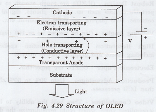
Working
1.
Forward bias voltage is applied across the OLED.
2.
By the applied voltage, the cathode gives electrons to the emissive layer.
3. The anode gets an electron from the conductive layer and produces a hole in the conductive layer as shown. in fig. 4.29.
4.
Thus, the emissive layer becomes rich in negatively charged particles
[electrons] and the conductive layer becomes rich in positively charged
particles [holes].
5.
Now, due to the electrostatic forces between these electrons and holes, they
come closer and recombine with each other.
6.
The recombination of electrons and holes occurs closer to the emissive layer.
In organic semiconductors, holes move faster than electrons.
7.
This recombination produces light and it is emitted through the transparent
substrate as shown in fig. 4.29.
Advantages
i.
Robust Design - OLED's are tough
enough to use in portable devices such as cellular phones, digital video
cameras, DVD players, car audio equipment etc.,
ii.
Viewing Angles - Can be viewed up to
160 degrees.
iii.
High Resolution - High information
applications including videos and graphics (Active matrix)
iv.
Electronic Paper - OLEDs are paper-thin.
v.
Production Advantages - Upto 20% to
50% cheaper than LCD processes.
vi.
Video Capabilities - They hold the
ability to handle streamlined video, which could revolutionize the display and
cellular phone market.
vii.
Power Usage - Takes less power.
Drawbacks
i.
The biggest technical problem for OLEDs is the limited lifetime of the organic
materials.
ii. The intrusion of water into displays can damage or destroy the organic materials.
iii.
Color - The reliability of the OLED is still not upto the bellso mark. After a
month of use, the screen becomes as nw non-uniform.
Applications
i.
OLED technology is used in commercial applications such as small screens for
mobile phones and portable digital audioplayers (MP3 players), car radios,
digital cameras and high-resolution micro displays for head-mounted displays.
ii.
They can be used in television screens, computer displays, advertising, information
and indication.
iii.
OLEDs can also be used in light sources for general space illumination and
large-area light-emitting elements.
Physics for Electronics Engineering: Unit IV: Optical Properties of Materials : Tag: : Construction, Working Principle, Band Structure diagram, Advantages, Drawbacks, Applications - Excitonic State & Organic Light Emitting Diode (OLED)
Physics for Electronics Engineering: Unit IV: Optical Properties of Materials
Under Subject

Physics for Electronics Engineering
PH3254 - Physics II - 2nd Semester - ECE Department - 2021 Regulation | 2nd Semester ECE Dept 2021 Regulation
Related Subjects

Professional English II
HS3251 2nd Semester 2021 Regulation | 2nd Semester Common to all Dept 2021 Regulation

Statistics and Numerical Methods
MA3251 2nd Semester 2021 Regulation M2 Engineering Mathematics 2 | 2nd Semester Common to all Dept 2021 Regulation

Engineering Graphics
GE3251 eg 2nd semester | 2021 Regulation | 2nd Semester Common to all Dept 2021 Regulation

Physics for Electrical Engineering
PH3202 2nd Semester 2021 Regulation | 2nd Semester EEE Dept 2021 Regulation

Basic Civil and Mechanical Engineering
BE3255 2nd Semester 2021 Regulation | 2nd Semester EEE Dept 2021 Regulation

Electric Circuit Analysis
EE3251 2nd Semester 2021 Regulation | 2nd Semester EEE Dept 2021 Regulation
Physics for Electronics Engineering
PH3254 - Physics II - 2nd Semester - ECE Department - 2021 Regulation | 2nd Semester ECE Dept 2021 Regulation

Electrical and Instrumentation Engineering
BE3254 - 2nd Semester - ECE Dept - 2021 Regulation | 2nd Semester ECE Dept 2021 Regulation

Circuit Analysis
EC3251 - 2nd Semester - ECE Dept - 2021 Regulation | 2nd Semester ECE Dept 2021 Regulation

Materials Science
PH3251 2nd semester Mechanical Dept | 2021 Regulation | 2nd Semester Mechanical Dept 2021 Regulation

Basic Electrical and Electronics Engineering
BE3251 2nd semester Mechanical Dept | 2021 Regulation | 2nd Semester Mechanical Dept 2021 Regulation

Physics for Civil Engineering
PH3201 2021 Regulation | 2nd Semester Civil Dept 2021 Regulation

Basic Electrical, Electronics and Instrumentation Engineering
BE3252 2021 Regulation | 2nd Semester Civil Dept 2021 Regulation

Physics for Information Science
PH3256 2nd Semester CSE Dept | 2021 Regulation | 2nd Semester CSE Dept 2021 Regulation

Basic Electrical and Electronics Engineering
BE3251 2nd Semester CSE Dept 2021 | Regulation | 2nd Semester CSE Dept 2021 Regulation

Programming in C
CS3251 2nd Semester CSE Dept 2021 | Regulation | 2nd Semester CSE Dept 2021 Regulation