Electronic Devices and Circuits: Unit II: Amplifiers
BJT Small Signal Model
Transistor as a Two Port Device, Small Signal Analysis, Analysis of CE Amplifier
Any two parameters are considered to be independent variables and the other two parameters are expressed in terms of the independent variables.
BJT SMALL SIGNAL MODEL
TRANSISTOR AS A TWO PORT DEVICE
A
transistor can be treated as a two-port network. The voltage and current at
port 1 are V1 and i1 and the voltage and current at port
2 are V2 and i2 as shown in Fig. 2.13. Any two parameters
are considered to be independent variables and the other two parameters are
expressed in terms of the independent variables.

Hybrid Parameters
The
hybrid or h parameters are used for analysis of the transistor.
If
the input current i1 and the output voltage V2are taken
as independent variables, then the input voltage V1 and output current
i2 are expressed in terms of i1 and V2.
Since
the units of the four parameters are completely different from each other,
these parameters are called hybrid parameters.
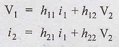
The
four hybrid parameters h11, h12, h21, h22
are defined as
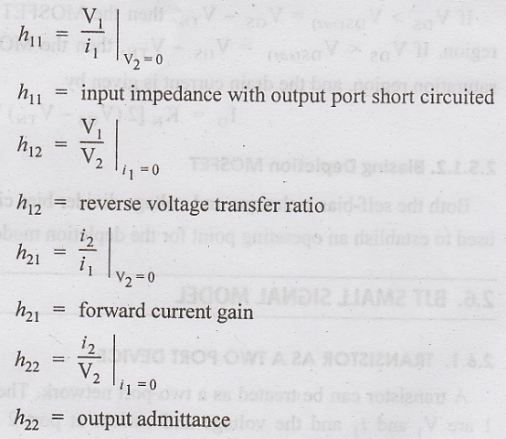
The
units of the h-parameters h11 and h22 are Ω and m ho respectively. h12 and h21
are dimensionless.
As
the units of h-parameters are different they are called hybrid parameters. The
values of h-parameters depend upon
1.
Transistor type
2.
Transistor configuration
3.
Operating point
4.
Frequency
5.
Temperature
Advantages of h-Parameters
i.
Easy to measure from static characteristics of transistor
ii.
Simple conversion from one configuration to other
iii.
Used upto radio frequencies
iv.
Convenient for circuit analysis and design
SMALL SIGNAL ANALYSIS
The
operation of an amplifiers in the mid band region of its frequency response is
analyzed. So it is also called midband analysis.
Assumptions
i.
All the coupling and bypass capacitors are equivalent to short circuit.
ii.
All the internal capacitances of the transistor are open circuited.
Steps
i.
Draw the ac equivalent circuit of the amplifiers.
ii.
Draw the hybrid equivalent circuit.
iii.
Calculate input impedance, output impedance, current gain, voltage gain and
power gain of the amplifier.
ANALYSIS OF CE AMPLIFIER
Let
us analysis the Common Emitter (CE) amplifier as follows
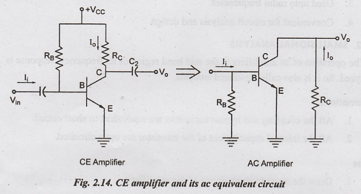
Step 1:
Draw ac equivalent circuit of the amplifier. Table 3.1 shows the ac equivalent
circuit for different de elements.

To
draw the ac equivalent circuit of the amplifier, the following steps should be
followed.
i.
Replace the dc voltage source by a short circuit.
ii.
Replace coupling and bypass capacitor by the short circuit.
Step 2:
Hybrid Equivalent Circuit

From
the ac equivalent circuit, the hybrid equivalent circuit can be obtained as the
ac shown in Fig. 2.15. The above Fig.2.15 can also be drawn as in Fig. 2.16 by connecting
the common ground.
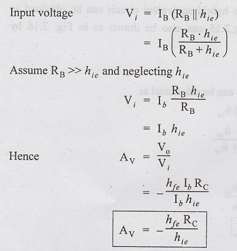
Input Impedance
From the Fig., the input impedance can be calculated as
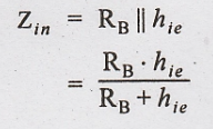
If RB >> hie, then

Output Impedance
It
is defined as the impedance determined with input voltage Vi = 0
From
Fig., if Vi = 0, then Ib = 0
⇒ hfe Ib
= 0
ie.,
the current source is open circuited
So 
Voltage Gain
Voltage
gain is defined as the ratio of output voltage to input voltage.
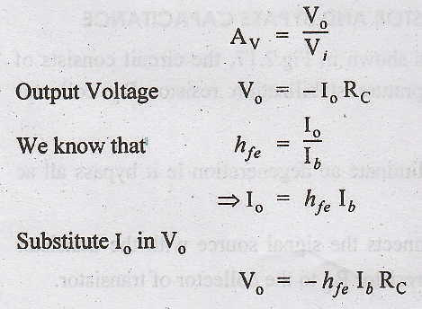
The
negative sign implies that there is 180° phase shift between input and output
signals.
Current Gain
Curent
gain is the ratio of output current to input current.

Electronic Devices and Circuits: Unit II: Amplifiers : Tag: : Transistor as a Two Port Device, Small Signal Analysis, Analysis of CE Amplifier - BJT Small Signal Model
Related Topics
Related Subjects

Electronic Devices and Circuits
EC3353 - EDC - 3rd Semester - ECE Dept - 2021 Regulation | 3rd Semester ECE Dept 2021 Regulation