Electronic Devices and Circuits: Unit II: Amplifiers
Biasing Method for BJT
Transistor Biasing
A common emitter amplifier using fixed bias circuit. The dc analysis of the circuit yields the following equation.
BIASING METHOD FOR BJT
TRANSISTOR BIASING
Fixed Bias (or) Base Resistor Method
A
common emitter amplifier using fixed bias circuit is shown in Fig. 2.6. The dc
analysis of the circuit yields the following equation.


Since
this equation is independent of current  and the stability factor
  is reduced to S
= 1 + β
is reduced to S
= 1 + β
Since
β is a large quantity, this is a very poor bias stable circuit. Therefore in
practice, this circuit is not used for biasing the base.
Advantages
(i)
Simplicity
(ii)
Small number of components required
(iii)
If the supply voltage is very large as compared to VBE of the
transistor, then the base current becomes largely independent of the voltage VBE
Collector to Base Bias (or) Biasing with Feedback Resistor
A
common emitter amplifier using collector to base bias circuit is shown in
Fig.2.7. This circuit is the simplest way to provide some degree of
stabilization to the amplifier operating point.

If
the collector current IC tends to increase due to either increase in
temperature or the transistor has been replaced by the one with a higher β, the
voltage drop across Re. increases, thereby reducing the value of VCE.
Therefore, IB decreases which in turn, compensates the increase in Ie.
Thus greater stability is obtained
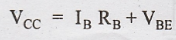
The
loop equation for this circuit is

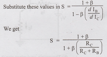
This
value of the stability factor is smaller than the value obtained by fixed bias
circuit. Also S can be made small and the stability can be improved by making RB
small or RC large.
If
RC is very small, then S = (β + 1), i.e., stability is very poor.
Hence the value of RC must be quite large for good stabilization.
Thus collector-to-base bias arrangement is not satisfactory for the amplifier
circuits like transformer coupled amplifier where the dc load resistance in
collector circuit is very small. For such amplifiers, emitter bias or self bias
will be the most satisfactory transistor biasing for stabilization.
Self Bias or Emitter Bias
A simple circuit used to establish a stable operating point is the self-biasing configuration. The self bias, also called as emitter bias, or emitter resistor and potential divider circuit, that can be used for low collector resistance, is shown in Fig.2.8.
The
current in the emitter resistor RE causes a voltage drop which is in
the direction to reverse bias the emitter junction. For the transistor to
remain in the active region the base emitter junction has to be forward biased.
The required base bias is obtained from the power supply through the potential
divider network of the resistance R1 and R2.

Use of Self Bias Circuit as a Constant Current Circuit
If
IC tends to increase, say due to increase in ICO with
temperature, the current in RE increases. Hence the voltage drop
across RE increases there by decreasing the base current. As a
result IC is maintained almost constant.
To Determine Stability Factor S
Applying
Thevenin's theorem to the circuit of Fig. 2.8 for finding the base current, we
have

The
loop equation around the base circuit can be written as

Differentiating
this equation with respect to Ic, we get

The
value of S is equal to one if the ratio RB/RE is very
small as compared to 1. As this ratio becomes comparable to unity, and beyond
towards infinity, the value of the stability factor goes on increasing till S =
1 + β.
This
improvement in the stability upto a factor equal to 1 is achieved as the cost
of power dissipation. To improve the stability, the equivalent resistance RB
must be decreased, forcing more current in the voltage divider network of R1
and R2.
Often
to prevent the loss of gain due to the negative feedback, RE is
shunted by a capacitor CE. The capacitive reactance XCE
must be equal to about one-tenth of the value of the resistance RE
at the lowest operating frequency.
Electronic Devices and Circuits: Unit II: Amplifiers : Tag: : Transistor Biasing - Biasing Method for BJT
Related Topics
Related Subjects

Electronic Devices and Circuits
EC3353 - EDC - 3rd Semester - ECE Dept - 2021 Regulation | 3rd Semester ECE Dept 2021 Regulation