Electrical and Instrumentation Engineering: Unit II: DC Machines
Universal Motor
Construction, Working Principle, Characteristics, Applications, Types
A universal motor is a special type of motor which is designed to run on either DC or phase AC supply. These motors are generally series wound (armature and field winding are in series), so it produce high starting torque.
UNIVERSAL MOTOR
Introduction
A
universal motor is a special type of motor which is designed to run on either
DC or phase AC supply. These motors are generally series wound (armature and
field winding are in series), so it produce high starting torque. Most of
universal motors are designed to operate at higher speeds exceeding 3500 rpm.
They run at lower sped on AC supply than they run on DC supply of same voltage,
due to the reactance voltage drop which is present in AC and not in DC.
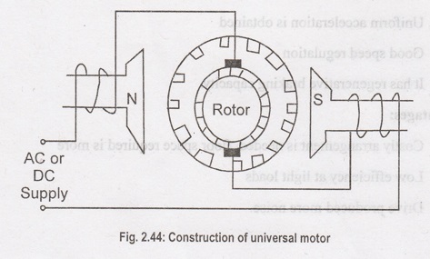
Construction of Unviersal Motors
Construction
of a universal motor is very similar to the construction of a DC machine. It
consists of a stator on which field poles are mounted. Filed coils are wound on
the field poles. However, the whole magnetic path (stator field circuit and
also armature) is laminated. Lamination is necessary to minimize the eddy
currents which induced while operating on AC. Unviersal motor is shown in
Figure 2.44
The
rotary armature is of wound type having straight or skewed slots and commutator
with brusher resting on it. The commutation on AC is poorer than DC because of
the current induced in coils. So that we are using brushes with high
resistance.
Working of Universal Motor
It
will works either in AC or DC supply. When the Universal motor is fed with a DC
supply, it works as a DC series motor. When current flows in the field winding
it produces an electromagnetic field. The same current also flows from the
armature conductors. When a current carrying conductor is placed in an
electromagnetic field, it experiences a mechanical force. Due to this
mechanical force or torque, the rotor starts to rotate. Its direction of force
is given by Fleming's left hand rule.
When
fed with AC supply, it still produces unidirectional torque. Because, armature
winding and field winding are connected in series, they are in same phase.
Hence, as polarity of AC changes periodically, the direction of current in
armature field winding reverses at the same time. Thus, direction of magnetic
field and the armature current reverses in such a way that the direction of
force experienced by armature conductors remains same. Irrespective of the
supply (AC or DC), universal motor works as a series motor work.
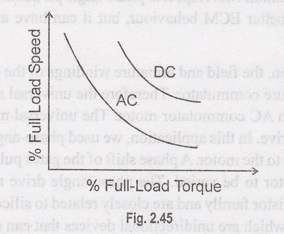
Speed/Load Characteristics
Speed/Load
Characteristics of a universal motor is similar to that of DC series motor. The
speed of a universal motor is low at full load and very high at no load.
Characteristics curve are shown in Figure 2.45.
Applications
1.
Home Applicance like vacuum cleaners, food mixers, domestic sewing machines.
2.
Higher rating universal motors are used in portable drills, blenders etc.
Speed Control of Universal Motor:
Speed
Control of Universal Motors can be possible by following ways
1.
Phase Angle Control
2.
PWM Chopper Control
In
Phase Control Method, Speed Control is achieved by varying the firing angle for
the TRIAC. Phase angle control is very cost effective solution but not very
efficient. In PWM method rectified AC line voltage is switched at a high
frequency by a Power MOFSET or IGBT device to generate time varying voltage for
the motor. In this method to control the motors by providing stable speed
control, preventing large currents and drawing minimum harmonic current from ac
mains supply are required. To meet these requirements using AC chopper with
current and speed feedback is preferred.
The
AC universal motor drive controls the rotation speed by means of phase angled
partialization. This method consists of changing the RMS voltage applied to the
motor. In case, the voltage is a function of the firing angle of the Tirac.
Continuous speed control of a universal motor running on DC is very easily
accomplished using a thyristor circuit. A thyristor supplies the motor during
the positive mains half cycle. Both the thristor and its control are connected
in such a way that the motor back EMF compensates the motor load variations to
adjust the speed. The pulse width modulation (PWM) technique, also known as
chopper drive is used to adjust the voltage applied to the motor. With the
variation of the PWM duty cycle, the effective voltage seen by the motor can be
changes. With the variations of the PWM duty cycle, the effective voltage seen
by the motor can be changed. The advantage of PWM modulation with respect to
phase-angle partialization is higher efficiency, less acoustic noise and better
ECM behaviour, but it can have an impact on brush life duration.
In
below application, the field and armature windings of the motor are connected
in series through the armature commutator. Therefore the universal motor is
also known as an AC series motor or an AC commutator motor. The universal motor
can be controlled either as a phase-angle drive. In this application, we used
phase-angle control technique to control the voltage given to the motor. A
phase shift of the gates pulses allows the effective voltage, seen by the motor
to be varied. The phase-angle drive requires just a TRIAC. These are part of
the thyristor family and are closely related to silicon controlled rectifiers.
However, unlike SCRS, which are unidirectional devices that can conduct current
only in one direction, TRIACS are bidirectional and so current can flow in
either direction, these are more commonly seen in circuits like motor drives.
TRIACS are usually seen in simple, low power applications like household dimmer
switches.
MOC3021
is an Optocouplers. An optocoupler connects input and output sides with a beam
of light modulated by input current. It transforms useful input signal into
light, sends it across the dieclectric channel, captures light on the output
side and transforms it back into electric signal. These are typically come in a
small 6 pin or 8 pin IC package, but are essentially a combination of two
distinct devices an optical transmitter, typically a gallium arsenide LED and
an optical receiver such as phototransistor or light triggered diac. The two
are separated by a transparent barrier which blocks any electrical current flow
between the two, but does allow the passage of light. The MOCS 3020 series
consists of gallium arsenide infrared emitting diodes, optically coupled to a
silicon bilateral switch. They are designed for applications requiring isolated
triac triggering.
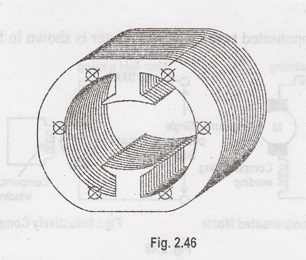
Types of Universal Motor
There
are two types of Universal Motor
i.
Non-Compensated Type with Concentrated Poles
ii.
Compensated Type with Distributed Field
iii.
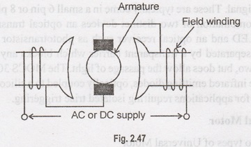
Non-Compensated Universal Motor
The
Non-Compensated Motor has two salient poles and it is laminated as shown in
figure 2.46.
The
armature is of wound type and the laminated core is either straight or skewed
slots. The leads of the armature winding are connected to the commutator. High
resistant brushed are used along with this type of motor to help better
commutation. An equivalent Non-Compensated Type Universal Motor is shown in
figure 2.47
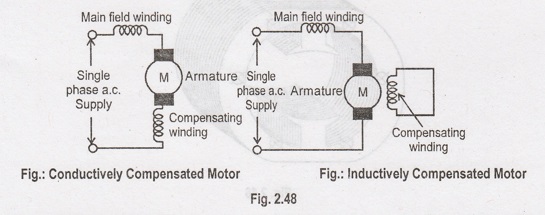
Compensated Type with Distributed
Field
The
compensated type Universal Motor consists of distributed field winding and the
stator core is similar to that of split-phase motor. We know that split phase
motors consists of an auxiliary winding in addition to main winding. Similar to
the split phase motors, the compensated type also consists of an additional
winding. The compensating winding helps in reducing the reactance voltage which
is caused due to alternating flux, when the motor runs with the AC supply.
An
equivalent compensated type Universal Motor is shown in figure 2.48.
Electrical and Instrumentation Engineering: Unit II: DC Machines : Tag: : Construction, Working Principle, Characteristics, Applications, Types - Universal Motor
Related Topics
Related Subjects

Electrical and Instrumentation Engineering
BE3254 - 2nd Semester - ECE Dept - 2021 Regulation | 2nd Semester ECE Dept 2021 Regulation