Electronic Devices and Circuits: Unit IV: Feedback Amplifiers and Oscillators
Types of Negative Feedback Connections
There are four different combinations i. Voltage - series feedback ii. Voltage - shunt feedback iii. Current-series feedback iv. Current - shunt feedback
TYPES OF NEGATIVE FEEDBACK CONNECTIONS
There
are four different combinations
i.
Voltage - series feedback
ii.
Voltage - shunt feedback
iii.
Current - series feedback
iv.
Current - shunt feedback
The
series feedback connections tend to increase the input resistance.
The
shunt feedback connections tend to decrease the input resistance.
The
voltage feedback tends to decrease the output resistance while the current
feedback tends to increase the output resistance.
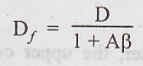
Decreased Distortion
Consider an amplifier with an open loop voltage gain and a total harmonic distortion D.
Then
with the introduction of negative feedback with the feedback ratio, β, the
distortion will reduce to
Decreased Noise:
There
are many sources of noise in an amplifier depending upon the active device used
with using the negative feedback ratio, β, the noise N can be reduced by a
factor of 1/1+Aβ in a similar manner to non-linear distortion.
Thus
the noise with feedback is given by
Nf
= N / 1+Aβ
Increase in Input Impedance
An
amplifier should have high input impedance so that it will not load the
preceding stage or the input voltage source. Such a desirable characteristic
can be achieved with the help of negative series voltage feedback. The input
impedance with feedback is given by
Zif
= Zi (1 + Aβ)
The
input impedance is increased by the factor of (1 + Aβ)
VOLTAGE SERIES FEEDBACK
A
block diagram of a voltage-series feedback is shown in Fig.4.2.
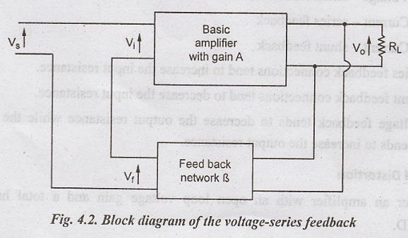
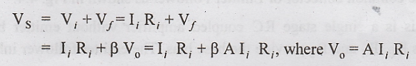
The
input to the feedback network is in parallel with the output of the amplifier.
A fraction of the output voltage through the feedback network is applied in
series with the input voltage of the amplifier. The shunt connection at the
output reduces the output resistance Ro. The series connection at
the input increases the input resistance. In this case, the amplifier is a true
voltage amplifier.
The
voltage feedback factor is given by β = Vf / Vo
Input and output Resistances
Fig.
4.3 shows the voltage series feedback circuit used to calculate input and
output resistances.
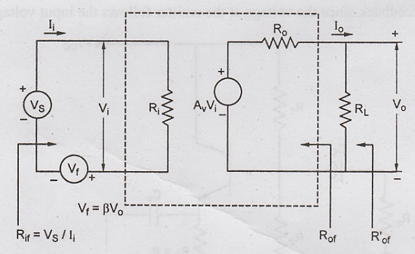
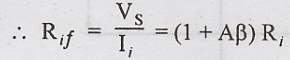
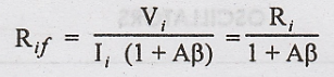
Hence
the input resistance of a voltage series feedback amplifier is given by
Rif
= (1 + Aβ) Ri
Where
Ri - the input resistance of the amplifier without feedback.
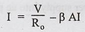
For measuring the output resistance, RL is disconnected and VS is set to zero. Then an external voltage V is applied across the output terminals and the current I delivered by V is calculated.
Then
Rof = V/I. Due to feedback, input voltage Vf reduces
output voltage A Vi which opposes V.
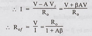
Ro
- The output resistance of the amplifier without feedback.
Emitter Follower
The
common collector or Emitter Follower as shown in Fig. 4.4.
This
is a single stage RC coupled amplifier without emitter bypass
capacitor across RE. R1 and R2 provide the
base bias. The emitter follower inherently exhibits 100% negative feedback since
the voltage at the emitter follows the input voltage.
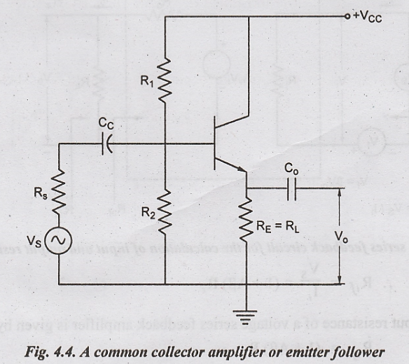
As
the output voltage is taken across RE = RL, the feedback
ratio, β = RE/RL = 1.
The overall voltage gain, Af = A / 1 + A, which is little less than unity.
The
emitter follower simultaneously increases input resistance and decrease output
resistance characteristics of an emitter follower.
VOLTAGE SHUNT FEEDBACK
A
voltage - shunt feedback is illustrated in Fig.4.5. It is called shunt-
derived, Shunt-feedback connection. Here a fraction of output voltage is
supplied in parallel with the input voltage through the feedback network.
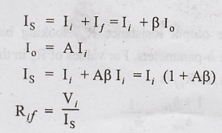
The
feedback signal If is proportional to the output voltage Vo.
Therefore the feedback factor is given by β = If /Vo.
This type of amplifier is called a trans-resistance
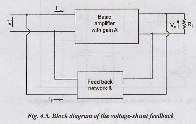
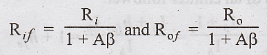
The
voltage-shunt feedback provides a stabilized overall gain and decreases both
input and output resistances by a factor (1 + Aβ).
Common Emitter Amplifier
with Voltage-Shunt Feedback
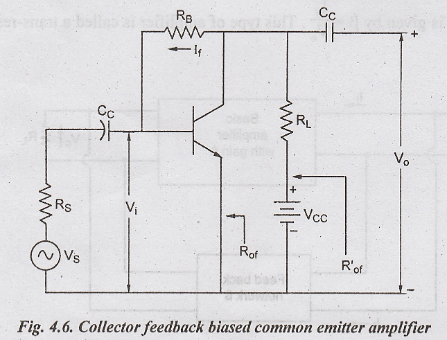
The
collector feedback biased common emitter amplifier as shown in Fig. 4.6. Here a
current which is proportional to the output voltage is feedback to the input.
Since
Vo >> Vi, the feedback current If ≈ Vo/RB,
so that the feedback ratio β ≈ 1/RB. The reduction in input and
output resistances occur due to Miller effect with RB.
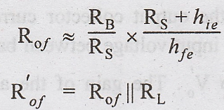
Hence,
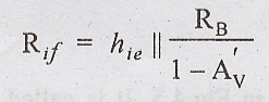
Where 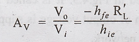
and 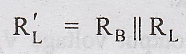
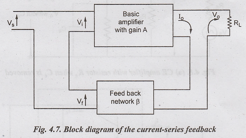
CURRENT-SERIES FEEDBACK
A
block diagram of a current-series feedback is illustrated in Fig.4.7. In
current- series feedback, a voltage is developed which is proportional to the
output current because of the series connection at the input and output, the
input and output resistances get increased.
This
type of amplifier is called transconductance amplifier. The transconductance
feedback
factor or ratio is given by β = Vf/Io
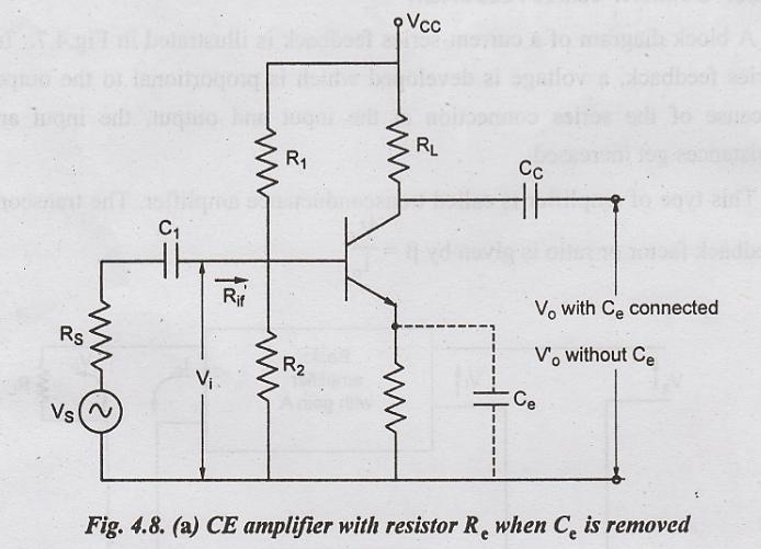
One
of the most common methods of applying the current- series feedback is to place
a resistor Re between the emitter lead of a common emitter amplifier
and ground. As the common emitter amplifier has a high gain, this is the most
often used with series negative feedback so that it can afford to lose some
gain. Such a circuit is illustrated in Fig.4.8.
When
Re is properly bypassed with a large capacitor Ce, the output
voltage is Vo and the voltage gain without feedback is A. Resistor Re
provides dc bias stabilization, but no an ac feedback when the capacitor Ce
is removed an ac voltage will be developed across Re due to the
emitter current flowing through Re and this
current is approximately equal to the output collector current. This voltage drop across Re will serve to decrease the input voltage between base and emitter. So that the output voltage will decrease to Vo'. The gain of the amplifier with negative feedback is now Af.
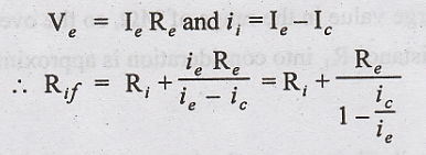
But
we know that 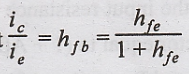
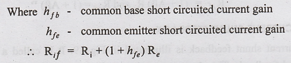
Thus,
we find that there is a large increase in the value of input resistance due to
negative feedback.
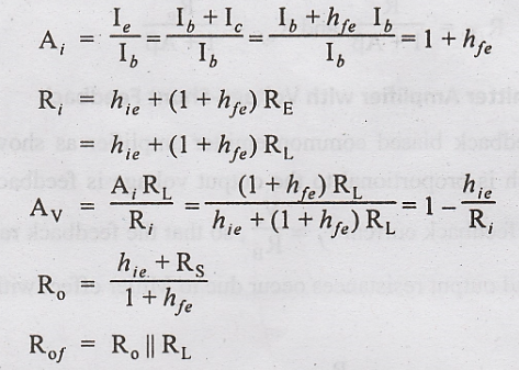
Input
resistance without feedback, Ri = hie
Rif
= hie + (1 + hfe) Re
If
the bias resistance, 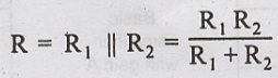 is considered the effective input
resistance with feedback is
is considered the effective input
resistance with feedback is 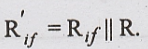
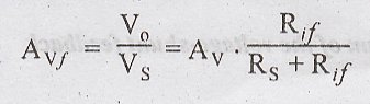
Voltage gain (Af)
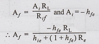
Voltage
gain without feedback, 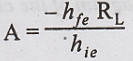
We
find that there is a large decrease in voltage gain due to negative feedback.
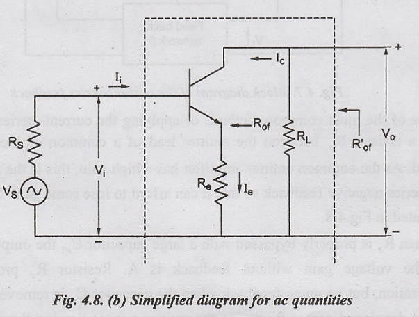
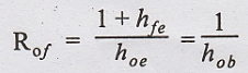
Output Resistance (Rof)
The
expression for the output resistance Rof looking back into the
collector involves RS, Re and all the h-parameters. For
values of Re in the order of RS and hie, an
approximate expression for Rof is
This
has usually a large value in the range of MΩ, so the overall output resistance
R'of taking the load resistance RL into consideration is
approximately RL.
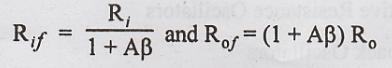
Note:
The
current series feedback increases the input resistance but decrease the output
resistance of a feedback amplifier by a factor equal to (1 + Aβ). Thus,
Rif
= (1 + Aβ) Ri and Rof = (1 + Aβ) Ro
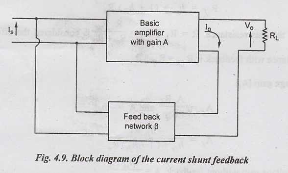
CURRENT-SHUNT FEEDBACK
A
current shunt feedback is illustrated in Fig.4.9. It is called a series
derived, shunt-fed feedback. The shunt connection at the input reduces the
input resistance and the series connection at the output increases the output
resistance. This is a true current amplifier. The current feedback factor is
given by β = If/Io
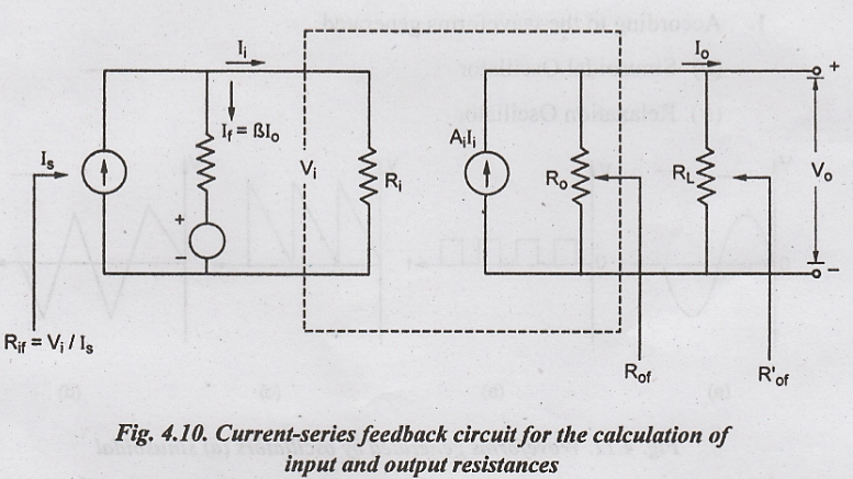
Input and Output Resistances
Fig.4.10
shows the current-shunt feedback circuit used to calculate input and output
resistances
For
measuring the output resistance, RL is disconnected and VS
is set to zero. Then external voltage V is applied across the output terminals
and the current I delivered by V is calculated.
Then
Rof = V/I
with
Is = 0, Ii = -If = -βIo = βI. Since current in
the output circuit due to feedback oppose the current I, due to applied voltage
V.
Simplifying
this, 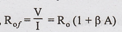
Thus
this type of feedback decreases the input resistance and increase the output
resistance i.e.,
As
this type of feedback has the least desirable effects, this connection will not
be considered at all practical applications.
Electronic Devices and Circuits: Unit IV: Feedback Amplifiers and Oscillators : Tag: : - Types of Negative Feedback Connections
Related Topics
Related Subjects

Electronic Devices and Circuits
EC3353 - EDC - 3rd Semester - ECE Dept - 2021 Regulation | 3rd Semester ECE Dept 2021 Regulation