Electrical and Instrumentation Engineering: Unit II: DC Machines
Torque Equation of DC Machines
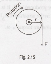
Torque is nothing but turning or twisting force about an axis. Torque is measured by the product of force and radius which the force acts. Consider a wheel of radius 'r' meters acted on by a circumferential force 'F' Newton
TORQUE EQUATION
Torque
is nothing but turning or twisting force about an axis. Torque is measured by
the product of force and radius which the force acts. Consider a wheel of
radius 'r' meters acted on by a circumferential force 'F' Newton as Figure
2.15.
Let
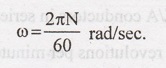
the force 'F' cause the wheel to rotate at 'N' rpm. The angular velocity of the
wheel
is:
Torque,
T = F x r N-m
Work
done per revolution = F x distance moved = F x 2πr joules.
Power
developed, P = Work done / Time = (F x 2πr) / Time for one revolution = (F x 2πr)
/ (60/N)
rps
= rpm/60 ; rps = N/60 ; time for one revolution = 60/N
P
= (F x r) 2πN/60
P=T
ω
Watts.
where,
T = torque in N - m
ω
= angular speed in rad/sec.
The
torque developed by a DC Motor is obtained by looking at the electrical power
supplied to it and mechanical power produced by it. It is also called armature
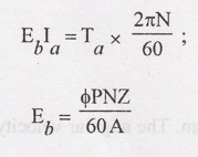
torque. The gross mechanical power developed in the armature is Eb Ia.
Then,
power in armature = Armature torque x ω.
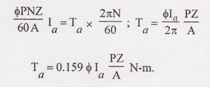
The
above equation is torque equation of a DC motors.
'T'
is proportional to φ Ia. Hence the torque of a given DC motor is
proportional to the product of the armature current and the flux.
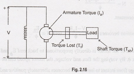
Shaft Torque (Tsh)
The
torque developed by the armature is called armature torque. It is denoted as Ta.
The full armature Torque is not available for doing useful work. Some amount of
torque is used for supplying iron and friction losses in the motor.
This
torque is called torque lost. It is denoted as Tf The remaining
torque is available in the shaft. It is used for doing useful work. This torque
is known as shaft torque. It is denoted as Tsh. The armature torque
is the sum of the torque lost and shaft torque.
Ta
= Tf + Tsh
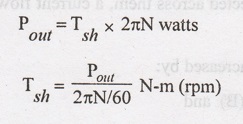
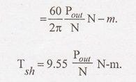
The
output power of the motor is:
Speed and Torque Equations
For
a DC motor, the speed equation is obtained as follows:
We
know,
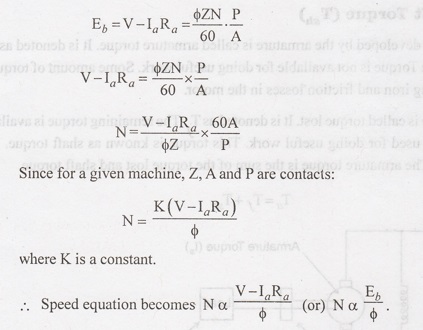
Hence
the speed of the motor is directly proportional to back emf Eb and
inversely proportional to flux φ. By varying the flux and voltage, the motor
speed can be changed.
The
emf change from instant to instant and becomes alternately positive and
negative. Such an emf is called an alternating emf. If the coil sides are
connected to two slip rings 'a' and 'b' and an external resistance R connected
across them, a current flows through the resistor, which is again alternating.
The
induced emf in the coil can be increased by:
Increasing
the flux density (B) and
Increasing the angular velocity (ω).
In
commercial generators a large number of coils are used and they are housed in
the armature, which rotates on a shaft at high speed.
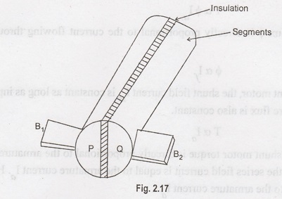
The
current flowing the external resistance to a DC generator is made
unidirectional by replacing the slip rings by replacing the slip rings by a
split rings. The ring is split into two equal segments are insulated from each
other and also from the shaft. The coil side AB is always attached to the
segment P and likewise CD to Q. It is indicated in Figure 3.9. The brushes B1
and B2 touch these segments and are meant to collect the current.
After
time "t" secs, the coil would have rotated through an angle of
radians in the anti-clockwise direction. The flux then linking with the coil is
B lb cos θ.
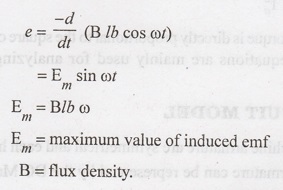
When
θ = 90°, the coil sides are moving at right angles to the flux lines. The flux
lines are cut at the maximum rate and the emf induced is maximum. When θ =
180°, the coil sides are again moving parallel to the flux lines (AB and CD
have exchanged) and the emf induced is zero once again. When θ = 270°, the coil
sides again move at right angles to the flux lines but their position reversed
when compared with θ = 90°. Hence the induced emf is maximum in the opposite
direction. When θ = 360°, the coil sides once again move parallel to the
magnetic field making the induced emf equal to zero. The coil has now come back
to the starting point.
If
the rotating of the coil is continued, the changes in the emf are again
repeated. For the two pole generator shown one complete cycle of changes occurs
in one revolution of the coil. The changes in voltage, 'e' with respect to the
angle or even time can be plotted.
The
torque equation of a DC motor is given by:
T
α φ Ia
Here,
the flux is directly proportional to the current flowing through the field
winding.
φ
α If
For
DC shunt motor, the shunt field current Ish is constant as long as
input voltage is constant. Therefore flux is also constant.
T
α Ia
So,
for DC shunt motor torque is directly proportional to the armature current. For
DC series motor, the series field current is equal to the armature current Ia.
Here, the flux φ is proportional to the armature current Ia.
Here
T α φ Ia becomes:
T
α Ia2
So,
for DC series motor, the torque is directly proportional to the square of the
armature current. The speed and torque equations are mainly used for analyzing
the various characteristics of DC motors.
Electrical and Instrumentation Engineering: Unit II: DC Machines : Tag: : - Torque Equation of DC Machines
Related Topics
Related Subjects

Electrical and Instrumentation Engineering
BE3254 - 2nd Semester - ECE Dept - 2021 Regulation | 2nd Semester ECE Dept 2021 Regulation