Electrical and Instrumentation Engineering: Unit II: DC Machines
Stepper Motor
Construction, Working Principle, Characteristics, Types, Advantages, Applications
Step Motors (often referred as stepper motors) are different from all other types of electrical drives in the sense that they operate on discrete control pulses received and rotate in discrete steps.
STEPPER MOTOR
Step
Motors (often referred as stepper motors) are different from all other types of
electrical drives in the sense that they operate on discrete control pulses
received and rotate in discrete steps. On the other hand ordinary electrical
A.C and D.C drives are analog in nature and rotate continuously depending on
magnitude and polarity of the control signal received. The discrete nature of
operation of a step motor makes it suitable for directly interfacing with a
computer and direct computer control. These motors are widely employed in
industrial control, specifically for CNC machines, where open loop control in
discrete steps are acceptable. These motors can also be adapted for continuous
rotation.
Construction
Step
Motors are normally of two types:
(a)
Permanent Magnet and
(b)
Variable Reluctance Type.
In
a step motor the excitation voltage to the coils is D.C. and the number of
phases indicates the number of windings. In both the two cases the excitation
windings are in the stator. In a permanent magnet type step motor the rotor is
a permanent magnet with a number of poles. On the other hand the rotor of a
variable reluctance type motor is of a cylindrical structure with a number of
projected teeth.
(a) Permanent Magnet Step Motor
The
principle of step motor can be understood from the basic schematic arrangement
of a small permanent magnet step motor is shown in Figure 2.49. This type of
motor is called a two-phase two-pole permanent magnet step motor; the number of
windings being two (phase 1 and phase 2) each split into two identical halves;
the rotor is a permanent magnet with two poles.

So
winding, A is split into two halves A1 and A2. They are
excited by constant D.C.voltage V and the direction of current through A1
and A2 can beset by switching of four switches Q1, Q2,
Q3 and where four switches are Q5 -Q8 are used
to control the direction of current as shown in Figure 2.50(b). The directions
of the currents and the corresponding polarities of the induced magnets are
shown in Figure 2.49 Q4 as shown in Figure 2.50(a). For example, if
Q1 and Q2 are closed, the current flows from A1
to A2, while closing of the switches Q3 and Q4
sets the direction of current from A2 to A1. Similar is
the case for the halves B1 and B2.

Now consider Figure 2.50. Let winding A be energized and the induced magnetic poles are as shown in Figure 2.51(a) we will denote the switching condition as (S1 = 1). The other winding B is not energized. As a result the moving permanent magnet will align itself along the axis of the stator poles as shown in figure (a). In the next step, both the windings A and B are excited simultaneously, and the polarities of the stator poles are as shown in Figure 2.51(b). We shall denote S1 = 1, for this switching arrangement for winding B. The rotor magnet will now rotate by an angle of 45° and align itself with the resultant magnetic field produced. In the next step, if we now make S1 = 0 (thereby de-energizing winding A), the rotor will rotate further clockwise by 45° and align itself along winding B, as shown in figure (c). In this way if we keep on changing the switching sequence, the rotor will keep on rotating by 45° in each step in the clockwise direction. The switching sequences for the switches Q1 to Q8 for first four steps are tabulated in Table 1.

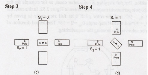


It
is apparent from Table 1 and Figure 2.52 that for this type of switching the
step angle is 45° and it takes 8 steps to complete a complete revolution. So we
have 8 steps/ revolution. It can also be seen from Table 1 that a pair of
switch (say Q7 – Q8) remains closed during consecutive
three steps of rotation and there is an overlap at every alternate step where
both the two windings are energized. This arrangement for controlling the step
motor movement is known as half stepping.
The direction of rotation can be reversed by changing the order of the
switching sequence.
It
is also possible to have an excitation arrangement where each phase is excited
one at a time and there is no overlapping where both the phases are energized
simultaneously, though it is not possible for the configuration shown in
Figure, since that will require the rotor to rotate by 90° in each step and in
the process, may inadventedly get locked in the previous position. But full
stepping is achievable for other cases, as for example for the two-phase
six-pole permanent magnet step motor as shown in Figure 2.52. In this case, the
stator pitch q1 = 90° and the rotor pitch θr = 60°; the
full step angle is given by θfs =θs, θr =
30°and the half step angle θhs = (θs – 0r)/2 =
15°. The desired direction of rotation can be achieved by choosing the sequence
of switching.

The
advantage of a permanent magnet step motor is that it has a holding torque. This means that due to the presence of permanent
magnet the rotor will lock itself along the stator pole even when the
excitation coils are de-energized. But the major disadvantage is that the
direction of current for each winding needs to be reversed. This requires more
number of transistor switches that may make the driving circuit unwieldy.
Another
way of reducing the number of switches is to use unipolar winding. In unipolar
winding, there are two windings per pole, out of which only one is excited at a
time. The windings in a pole are wound in opposite direction, thus either
N-pole or S-pole, depending on which one is excited.
(b) Variable Reluctance Type Step Motor
Variable
reluctance type step motors do not require reversing of current through the
coils, but at the same time do not have any holding torque. Compared to
permanent magnet step motors, their step angles are also much smaller. Step
angle as low as 1.8° can be achieved with this type of motors. Here the rotor
is a cylindrical soft iron core with projected teeth. When a particular stator
coil is excited, the rotor aligns itself such that one pair of teeth is along
the energised stator coil, at the minimum reluctance path. The schematic
arrangement of a three phase VR motor with 12 stator poles (teeth) and eight
rotor teeth is shown in Figure 2.53.
When
phase-I is energized, the rotor will align itself as shown in the Figure 2.53.
In the next step, if phase-1 is switched off and phase-2 is switched on, the
rotor will rotate in CCW direction by an angle of 15°. This can be understood
from the following derivation:
Here
the stator pole pitch

Similar
to the earlier case, we can also have half
stepping where step angle of 7.5° can be achieved. To switching sequence
for rotation in the counter clockwise direction will half stepping would be
1-(1,2) – 2 - (2, 3) – 3 - (3, 1) - 1 ....
Further
reduction of step angle is possible by increasing the number of stator and
rotor teeth. Besides, multi-stack stators are also used for achieving smaller
step angle, where there are several stacks of stator windings skewed from each
other by a certain angle. It has been already mentioned that the VR motors do
not have any holding torque. It is natural because, when the stator coils are
de-energised there is no magnetic force present and the rotor is free. Hybrid step motors are improved versions
of single stack. VR motors, where the basic constructions are modified slightly
in order to achieve holding torque. However this part will not be discussed in
this lesson. Interested readers may consult the books given in the reference.

Fig. 2.53: Three-phase single-stack VR step motor with twelve stator poles (teeth) and eight rotor teeth
Hybrid Stepper:
The
hybrid stepper motors have the combination of the best properties of variable
reluctance and permanent magnet steppers, so they are more expensive than the
PM stepper motor. The hybrid type stepper motors provide better performance
with respect to step resolution, torque and speed.
The
rotor of a hybrid stepper is multi-toothed like the variable reluctance
steppers and it contains an axially magnetized concentric magnet around its
shaft. The teeth on the rotor provide an even better path which helps guide the
magnetic flux to preferred locations de an even b in the air gap.
The
most commonly used types of stepper motors are the hybrid and permanent magnet.
The designers prefer permanent magnets unless their project requires the hybrid
steppers, since the cost of permanent magnet are less than of hybrids.

Advantages of Stepper Motor:
1.
The rotation angle of the motor is proportional to the input pulse.
2.
The motor has full torque at standstill.
3.
Precise positioning and repeatability of movement since good stepper motors
have an accuracy of 3-5% of a step and this error is non-cumulative from one
step to the next.
4.
Excellent response to starting, stopping and reversing.
5.
Very reliable since there are no contact brushes in the motor. Therefore the
life of the motor is simply dependent on the life of the bearing.
6.
The motors response to digital input pulses provides open-loop control, making
the motor simpler and less costly to control.
7.
It is possible to achieve very low speed synchronous rotation with a load that
is directly coupled to the shaft.
8.
A wide range of rotational speeds can be realized as the speed is proportional
to the frequency of the input pulses.
Applications:
1.
Industrial Machines - Stepper motors
are used in automotive gauges and machine tooling automated production equipments.
2.
Security - New surveillance products
for the security industry.
3.
Medical - Stepper motors are used
inside medical scanners, samplers, and also found inside digital dental
photography, fluid pumps, respirators and blood analysis machinery.
4.
Consumer Electronics - Stepper
motors in cameras for automatic digital camera focus and zoom functions. And
also have business machines applications, computer peripherals applications.
Disadvantages:
1.
Once motor is not controlled well, it can easily cause resonance vibration.
2.
Hardly to run to the higher speed.
Characteristics of Stepper Motor
The
stepper motor characteristics are classified as:
1.
Static characteristics and
2.
Dynamic characteristics
The
static are at the stationary position of the motor while the dynamic are under
running conditions of the motor.
(a) Static Characteristics
These
characteristics include:
1.
Torque displacement characteristics
2.
Torque current characteristics.
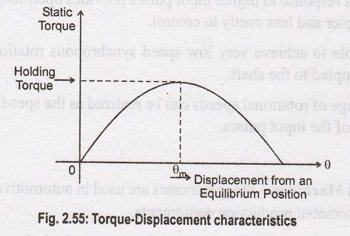
1. Torque-Displacement
characteristics:
This
gives relationships between electromagnetic torque developed and displacement
angle from steady state position. These characteristics are shown in the Figure
2.55.
2. Torque-Current Characteristics:
The
holding torque of the stepper motor increases with the exciting current. The
relationship between the holding torque and the current is called as
torque-current characteristics. These characteristics are shown in the Figure
2.56.

(b) Dynamic Characteristics
The
stepping rate selection is very important in proper controlling of the stepper
motor. The dynamic characteristics gives the information regarding torque
stepping rate. These are also called torque stepping rate curves of the stepper
motor. These curves are shown in the Figure 2.57.

When
stepping rate increases, rotor gets less time to drive the load from one
position to other. If stepping rate is increased beyond certain limit, rotor
cannot follow the command an starts missing the pulses.
Now
if the values of load torque and stepping rate are such that point of operation
lies to the left of curve I, then motor can start and synchronize without
missing a pulse.
For
example, for a load torque of T'L, the stepping rate selection should be less
than f1 so that motor can start and synchronize, without missing a
step. But the interesting thing is that once motor has started and
synchronized, then stepping rate can be increased e.g., upto f2 for
the above example. Such as increase in stepping rate from f1 to f2s
without missing a step and without missing the synchronism. But beyond f2,
if stepping rate is increased, motor will loose its synchronism.
So
point A as shown in the figure indicates the maximum starting stepping rate or
maximum starting frequency. It is defined as the maximum stepping rate with
which unloaded motor can start or stop without loosing a single step. While
point B as shown in the figure indicates the maximum slowing frequency. It is
defined as the maximum stepping rate which unloaded motor continues to run
without missing a step. Thus area between the curves I and II shown hatched
indicates, for various torque values, the range of stepping rate which the
motor can follow without missing a step, provided that the motor is started and
synchronized. This area of operation of the stepper motor is called slew range.
The motor is said to be operating in slowing mode.
It
is important that in a slew range the stepper motor can not be started, stopped
or reversed without losing steps. Thus slew range is important for speed
control application. In position control, to get the exact position the motor
may be required to be stopped or reversed. But is not possible in a slew range.
Hence slew range is not useful for position control applications.
To
achieve the operation of the motor in the slew range motor must be accelerated
carefully using lower pulse rate. Similarly to stop or reverse the motor
without loosing acceleration and deceleration of the stepper motor, without
losing any step is called ramping.
Important Definitions
1.
Holding Torque: It is defined as the
maximum static torque that can be applied to the shaft of an excited motor
without causing a continuous rotation.
2.
Detent Torque: It is defined as the
maximum static torque that can be applied to the shaft of an unexcited motor
without causing a continuous rotation. Under this torque the rotor comes back
to the normal rest position even if excitation ceases. Such positions of the
rotor are referred as the detent positions.
3.
Step Angle: It is defined as the
angular displacement of the rotor response to each input pulse.
4.
Critical Torque: It is defined as
the maximum load torque at which rotor does not move when exciting winding is
energized. This is also called pullout torque.
5.
Limiting Torque: It is defined for a
given pulsing rate or stepping rate measured in pulses per second, as the
maximum load torque at which motor follows the control pulses without missing
any step. This is also called pull in torque.
6.
Synchronous Stepping Rate: It is
defined as the maximum rate at which the motor can step without missing Steps.
The motor can start, stop or reverse at this rate.
7.
Stewing Rate: It is defined as the
maximum rate at which the motor can step unidirectionally. The stewing rate is
much higher than the synchronous stepping rate. Motor will not be able to stop
or reverse without missing steps at this rate.
Electrical and Instrumentation Engineering: Unit II: DC Machines : Tag: : Construction, Working Principle, Characteristics, Types, Advantages, Applications - Stepper Motor
Related Topics
Related Subjects

Electrical and Instrumentation Engineering
BE3254 - 2nd Semester - ECE Dept - 2021 Regulation | 2nd Semester ECE Dept 2021 Regulation