Electrical and Instrumentation Engineering: Unit III: AC Rotating Machines
Starting Methods of Single phase induction motors
Types
Single phase induction motors are named according to the starting Methods (or) device employed. So based on starting methods, the various types of single phase induction motors are explained
STARTING METHODS
Single
phase induction motors are named according to the starting Methods (or) device
employed. So based on starting methods, the various types of single phase
induction motors are
1.
Split phase Motor
2.
Capacitor Motor
(i)
Capacitor Start Motor
(ii)
Capacitor run Motor
(iii)
Capacitor start and capacitor run Motor
3.
Shaded Pole Motor
4.
Reluctance Motor
Split Phase Motors
The
stator of the split phase induction motor consits of two windings. One is known
as starting or auxiliary winding and the another is called as main or running
winding. Both the windings are placed in the stator slots but starting winding
is displaced in space b 90°, with the main winding on the stator slots, so as
to create at start a condition similar to two-phase machine, which will enable
the Single Phase motor to produce rotating magnetic field at starts. Connection
diagram of both the windings has been shown in Fig.3.39.


Further
the windings are designed in such a manner that main winding is highly
inductive and the auxillary winding has a greater resistance.
When
the motor is connected to single phase supply it trans current, I which is the
vector sum of currents flowing through both the windings. Since starting
winding has more resistance single of lags of starting winding correct, Is
is less as compared to the??? Winding current, In (See fig 3.39(b)). The angle
between the two corrects, e is called torque angle, so starting torque produced
is proportional to sing and motor will no have high starting torque if 0 is
approaching to 90°. Generally in split phase motor ne auxiliary winding is
disconnected, when the motor picks up speed. This is achieved by mi connecting
a centrifugal switch or time lag relay in series with auxiliary windings.
90/This switch or device is normally closed type and when motor picks up speed,
near to about 80% it opens automatically with centrifugal force in case of
centrifugal switch and due to time adjustment in case of TDR (i.e. Time Delay
Relay). Thus puts the starting winding out of the circuit.
Split
phase motor generally heve starting torque about twice the full load torque of
the motor. Its typical torque speed curve has been shown in Fig.5.14. The curve
clearly shows, the starting torque, the speed at which centrifugal switch or
such device operates and its normal running region. Other important information
related to its performance are:
1.
Its starting current is about 6 to 8 times of the full load current.
2.
Its slip is about 5% to 7% which is higher than 30 induction motor. Because in
1f motors, an average Torque becomes zero little earlier than synchronous
speed. See Fig.3.40. Therefore all single phase induction motors have greater
slip as compared to three phase induction motors.
3.
Its power factor is low, which is about 0.6 at full load.
4.
Its full load efficiency is about 60% to 65%.
5.
For the same frame size its rating is about 60% as compared to that of
polyphase motor.
6.
Split phase motors are generally designed for 4 pole, 230V, 50Hz, 1f supply
system.
Applications:
i.
Drills
ii.
Press burners
iii.
Fans
iv.
Blowers
v.
Washing Machines
vi.
Centifugal Pumps
vii.
Grinders
viii.
Wood working tools
Capacitor Motors
The
stator of the capacitor motors also has two windings like split phase induction
motor i.e. starting winding and running winding. But in this motor phase angle
between the currents of man and starting winding is obtained by connecting a
capacitor in series with the starting winding. Circuit and not by keeping the
difference of resistance and reactance with ???. In fact capacitor motor is
also a split phase motor but, it is in the improved forms and may be called as
split phase capacitor motor. The use of capacitor has may advantages such as
1.
The starting torque is much higher as compared to usual split phase motor as
the torque angle is about 90°.
2.
Starting live current is less.
3.
Power factor of the motors gets improved.
The
capacitors may be connected in series with the starting winding in three different
ways. There fore, there are three types of capacitor motors.
i. Capacitor
start motor
As
shown in Fig.3.41 this motor has one dry type electrolytic capacitor which is
specially designed for ac and is connected with centrifugal switch in series
with the starting winding. As discussed in the case of resistance split-phase
induction motor the centrifugal switch of this motor will also disconnect the
starting winding, once the motor has picked up speed-say upto 80% of its
synchromy speed. The starting capacitors used are designed for definite duty
cycle and not for continuous use. So a faulty centrifugal switch ????.
The
number of times of the starting winding is more in this motor as compared to
starting winding turns used in resistance split-phase motor. This leads to
large number of ampere times, providing large rotating flux and high starting
torque. The typical torque - speed characteristic of this type of motor has
been shown in Fig.3.42


Other
important informations related to its performance are:
1.
Its starting current is about 4 to 5 times of its full load current.
2.
Its slip is about 5%
3.
Its power factor is high at starting but low when running. Its full-load factor
is about 0.65.
4.
Its full-load efficiency is about 65%
5.
In this motor angle q between the furo current is nearly 90° at start (see box
fig.3.41(b)) so motor has more starting torque as compared to split-phase
motors.
Applications
1.
Pumps
2.
Compressors
ii. Capacitor
Run Motor
In
this motor also as shown in Fig.3.42 (a) a capacitor is connected in series of
the starting winding. No centrifugal switch or other such device has been used
for disconnecting the starting winding. As the starting winding remains
connected with the supply it is designed similar to running winding. The
capacitor used in this type of motor is also of full time rating as it will
always be in the series of starting winding. Paper speed oil filled type
capacitor are used in this type of motor.

In
this motor also as shown in Fig.3.42 (b) the time-phase difference between two
currents is nearly 90°, so the starting torque of this motor is also higher and
the rotating field produced will be a uniform one, thus providing noise less
operation.
The
capacitor remains in the circuit so resultant line current is less, power
factor is high, which is nearly unity.
Its
full load efficiency will be higher, about 75%. Fig 3.43 shows its typical
forque speed characteristics.

Applications
1.
Fans
2.
Room Coolers
3.
Portable tools
iii. Capacitor
Start and Capacitor Run Motor
When
high starting torque is required as lampared to capacitor run motor and the
advantages of keeping the capacitor in the circuit is also to be achieved then
instead of using one capacitor two capacitors of different ratings are
employed.
As
shown in Fig.3.44(a), one capacitor m series which centrigual switch or other
such device and another capacitor is permanently connected in the starting
winding circuit.
When
motor is connected to single phase supply, similar to Capacitor start motor,
centrifugal switch will disconnect the capacitor in its circuit and now the
motor will be operating like capacitor run motor. Hence the motor drives the
name, capacitor start and capacitor run motor. For Phasor diagram, see
Fig.3.44(b)

The
value of the capacitor, in the circuit of centrifugal switch i.e., starting
capacitor, is large, about 80 μF to 300 μF and it is of electrolytic type. The
running capacitor is of low value, about 3 μF to 16 μF and it is an oil
impregeated paper type capacitor.
Hence
in order to have both, high starting torque and better operating power factor,
capacitor start and capacitor run motor can be used.
Fig.3.45
shows the torque-speed (or slip) characteristic. Starting torque of this motor
is about 300% of full load torque. Resultant line current is low and power
factor is high, but its cost is also high.
Applications
1.
Loaded Conveyors
2.
Compressors
3.
Reciprocating pumps
4.
Stokers
This
motor is used when high starting torque is required.

The
direction of rotation of all the split phase motors, whether resistance split
phase motor or split phase capacitor motors, can be reversed by interchanging
the connections of the supply to either of the starting winding or of the
running winding.
Shaded pole motor
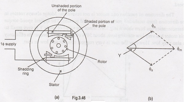
The
stator of the motor has salient poles with saw cut at about 1/3rd position of
the pole and is surrounded by a coppering usually called as shading band, see
Fig.3.46(a). Poles of shaded pole motor carry single phase ac winding known as
field winding.

The
rotor of this motor is generally squirrel cage type but keeping in mind the
cost of the motor, for very small rating shaded pole motors, solid core can
also be used. The rating of the motor is so less that more than 50% of power is
lost. It will not produce appreciable heat and there is no appreciable increase
in the electricity bill.
When
ac supply is gives to the station terminals, alternating flux is produced. This
flux will induce short circuit correct in the shading band by transformer
action. This flux of shading band, according to Lenz's law will not allow the
flux to rise at area in this portion, but will take some time to attaining
certain value. When current through main winding decreases, again shading band
will not allow the field to dk out quickly. Thus, creating
time-phase-displacement between the fluxes of unshaded portion and shaded
portion.
Let
fs is the flux in shaded portion, fn represents the flux
in unshaded portion of the pole and fm is the main pole flux. The
relation between these fluxes has been shown in Fig.3.46 (a).
In
this motor flux does not rotate through 360° but appears to sweep over pole-
faces from unshaded portion to shaded portion. Under the influence of this flux
small starting torque, as the angle between fs and fn is
very small, is produced. As soon as rotor starts rotating due to single phase
induction motor action, additional torque is produced and rotor rotates
continuously with the speed little less than the synchronous speed.
The
direction of rotation of the motor is not reversible. Motor always rotates in
the direction from unshaded portion to the shaded portion. The typical
speed-torque characteristics has been shown in Fig.3.47. Since the value of
angle Y is very small so this motor has very low starting torque, about 50% of
its full load torque. Its efficiency is also very low. However the motor is
very rugged, reliable and low in cost.

Applications
i.
Small fans
ii.
Electric clocks
iii.
Hair dryers
iv.
Grama phones
Electrical and Instrumentation Engineering: Unit III: AC Rotating Machines : Tag: : Types - Starting Methods of Single phase induction motors
Related Topics
Related Subjects
Electrical and Instrumentation Engineering
BE3254 - 2nd Semester - ECE Dept - 2021 Regulation | 2nd Semester ECE Dept 2021 Regulation
