Electrical and Instrumentation Engineering: Unit II: DC Machines
Starters
Types, Necessity, Working Principle, Construction | DC Motors
DC motors are self-starting motors, whenever the armature and field winding of a DC motor receives supply, motoring action takes place. So, DC motors do not require any additional device to start it.
STARTERS
Introduction
DC
motors are self-starting motors, whenever the armature and field winding of a
DC motor receives supply, motoring action takes place. So, DC motors do not
require any additional device to start it.
Necessity
of Starter
When
a de motor is started with full voltage applied across its armature terminals
during the starting period, it will draw more current than its rated current.
This excessive current will overheat the armature winding and may even damage
the winding. During starting period, a variable resistance called a starter is
connected in series with the armature circuit to limit the starting current.
Starting
of DC Motors
Voltage
equation Eb = V - Ia Ra
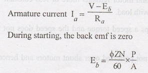
It
speed is zero, back emf is also zero. For example, we assume that Ra
value is 0.5 Ω. The supply voltage is 220 V. Power rating of the motor is 7500
W.
Then,
the armature current
Ia
= V / Ra = 220 / 0.5 = 440 A.
But
the full-load current:
IL
= 7500 / 220 = 34 A.
Without
using starter, if the motor is started directly, the starting current is around
13 times of the full-load current.
Thus
the absence of back emf causes the armature current as the time of starting to
shoot up to about (13 to 15) times the normal armature current.
Sudden
drawing of this large current from the supply system is unwarranted. It causes
sudden drop in voltage of the supply system.
This
voltage drop affects the other loads connected in the system. However, this
large current exists only for a brief period.
Just
at the time of closing the supply to the armature, as and when the armature
pick its speed, the back emf starts increasing and the armature current will
come down.
The
difficulty is that the circuit breaker may not be able to withstand this large
current and it may open the supply connection.
In
order to start and accelerate the motor within a reasonable time, it may be
enough to have 2 to 3 times the rated current as the starting current.
Therefore,
to limit the starting current, an additional resistance Rst should
be added in series with the armature circuit.
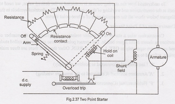
Two-point Starter
A
two-point starter is used for starting de motor which has the problem of over-
speeding due to loss of load from its shaft. Such a starter is shown in
fig.2.37
Here
for starting the motor, the control arm is moved clockwise from its OFF
position to the ON position against the spring tension. The control arm is held
in the ON position by an electromagnet. The hold-on electromagnet is connected
in series with the armature circuit. If the motor losses its load, current
decreases and hence the strength of the electromagnet also decreases. The
control arm returns to the OFF position due to spring tension, this preventing
the motor from overspending. The starter arm also returns to the OFF-position
when the supply voltage decreases appreciably. L and F are two points of the
starter which are connected with the supply and motor terminals.
3 Point Starter
A
3 point starter is a device that
helps in the starting and running of a DC shunt motor or compound wound DC
motor (similar to a 4 point starter). Now the question is why these types of DC
motors require the assistance of the starter in the first place? Well, it's due
to the presence of back emf (Eb), which plays a critical role in
governing the operation of the motor. The back emf develops as the motor
armature starts to rotate in presence of the magnetic field, by generating
action and counters the supply voltage. Hence the back emf at the starting of
the motor is zero, but it develops gradually as the motor gathers speed.
The
general motor emf equation is:
E
= Eb + Ia Ra
Where
E - Supply Voltage; Eb - Back EMF; Ia - Armature Current;
and Ra = Armature Resistance. Since at starting Eb = 0,
then E =Ia Ra. Hence we can rearrange for the armature
current Ia:
Ia
= E / Ra
We
can see from the above equation that the current will be dangerously high at
ort or we can starting (as the armature resistance Ra is small).
This is why it's important that we make use of a device like the 3 point starter to limit the starting
current to acceptably low value.
To
understand how the starting current is restricted to the desired value, we need
to look at the construction and working
of three-point starter. The electrical symbols in the diagram below show
all the essential parts of a three-point starter.
Construction of 3 Point Starter
Construction
wise a starter is a variable resistance, integrated into the number of sections
as shown in the figure beside. The contact points of these sections are called
studs and are shown separately as OFF,
1, 2, 3, 4, 5, RUN. Other than that there are three main points, referred
to as
1.
'L' Line terminal (Connected to positive of supply)
2.
'A' Armature terminal (Connected to the armature winding)
3.
'F' Field terminal (Connected to the field winding)
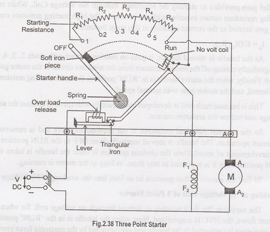
And
from there it gets the name 3 point starter. Now studying the construction of 3 point starter in
further details reveals that the point 'L' is connected to an electromagnet
called overload release (OLR) as shown in the figure. The other end of OLR is
connected to the lower end of conducting lever of starter handle where spring
is also attached with it, and the starter handle also contains a soft iron
piece housed on it. This handle is free to to move to the other side RUN
against the force of the spring. This spring brings back the handle to its
original OFF position under the influence of its own force. Another parallel
path is derived from the stud '1', given to another electromagnet called No
Volt Coil (NVC) which is further connected to terminal 'F.' The starting
resistance at starting is entirely in series with the armature. The OLR and NVC
act as the two protecting devices of the Starter
Working of Three Point Starter
Having
studied its construction, let us now go into the working of the 3 point starter. To start with the handle is in the
OFF position when the supply to the DC motor is switched on. Then handle is slowly
moved against the spring force to make contact with stud No. 1. At this point,
field compound motor gets supply through the parallel path provided to starting
the resistance, through No Voltage Coil. While entire starting resistance comes
in series with the armature. The high starting armature current thus gets
limited as the current equation at this stage becomes:
Ia
= E / (Ra + Rst)
As
the handle is moved further, it goes on making contact with studs 2, 3, 4,
etc., thus gradually cutting off the series resistance from the armature
circuit as the motor gathers speed. Finally, when the starter handle is in
'RUN' position, the entire starting resistance is eliminated, and the motor
runs with normal speed.
This
is because back emf is developed consequently with speed to counter the supply
voltage and reduce the armature current.
So
the external electrical resistance is not required anymore and is removed for
optimum operation. The handle is moved manually from OFF to the RUN position
with the development of speed. Now the obvious question is once the handle is
taken to the RUN position how it is supposed to stay there, as long as the
motor is running.
To
find the answer to this question let us look into the working of No Voltage
Coil.
Working of No Voltage Coil of 3 Point Starter
The
supply to the field winding is derived through no voltage coil. So when field
current flows, the NVC is magnetized. Now when the handle is in the 'RUN'
position, a soft iron piece is connected to the handle and gets attracted by
the magnetic force produced by NVC, because of flow of current through it. The
NVC is designed in such a way that it holds the handle in 'RUN' position
against the force of the spring as long as supply is NVC holds the handle in
the 'RUN' position and hence also called hold
on coil.
Now
when there is any kind of supply failure, the current flow through NVC is
affected and it immediately loses its magnetic property and is unable to keep
the soft iron piece on the handle, attracted. At this point under the action of
the spring force, the handle comes back to OFF position, opening the circuit
and thus switching off the motor. So due to the combination of NVC and the
spring, the starter handle always comes back to OFF position whenever there is
any supply problem. Thus it also acts as a protective device safeguarding the
motor from any kind of abnormality.
Drawbacks of a Three Point Starter
The
3 point starter suffers from a
serious drawback for motors with a large variation of speed by adjustment of
the field rheostat. To increase the speed of the motor field resistance can be
increased. Therefore current through the shunt field is reduced.
Field
current becomes very low which results in holding electromagnet too weak to
overcome the force exerted by the spring. The holding magnet may release the
arm of the starter during the normal operation of the motor and thus disconnect
the motor from the line. This is not desirable. A 4 point starter is thus used
instead, which does not have this drawback.
4 Point Starter
A
4 point starter protects the armature
of a DC shunt motor or compound wound DC motor against the initially high
starting current of the DC motor. The 4 point starter has a lot of
constructional and functional similarity to a 3 point starter, but this special
device has an additional point and coil in its construction (as the name
suggests). This brings about some difference in its functionality, though the
basic operational characteristic remains the same. The basic difference in the
circuit of a 4 point starter as
compared to 3 point starter is that the holding coil is removed from the shunt
field current and is connected directly across the line with current limiting
resistance in series.
Now
to go into the details of the operation
of 4 point starter, let's have a look at its construction diagram. This
will help demonstrate the difference between a 4 vs 3 point starter.
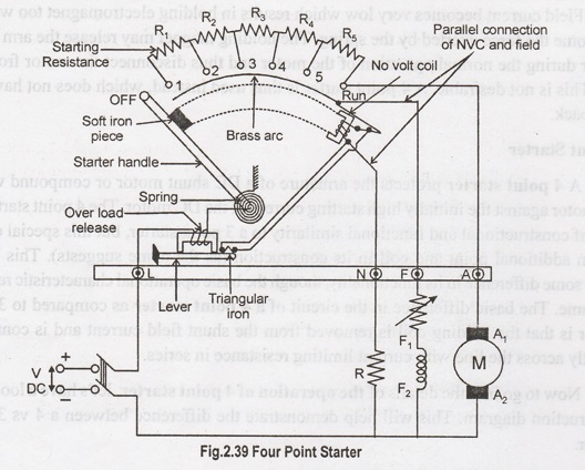
Construction and Operation of Four Point Starter
A
4 point starter as the name suggests has 4 main operational points, namely
i.
'L' Line terminal (Connected to positive of supply.)
2.
'A' Armature terminal (Connected to the armature winding.)
3.
'F' Field terminal. (Connected to the field winding.)
4.
Like in the case of the 3 point starter, and in addition to it there is,
A
4th point N (Connected to the No Voltage Coil NVC)
The
remarkable difference in case of a 4 point starter is that the No Voltage Coil
is connected independently across the supply through the fourth terminal called
'N' in addition to the 'L', 'F' and 'A'. As a direct consequence of that, any
change in the field supply current does not bring about any difference in the
performance of the NVC. Thus it must be ensured that no voltage coil always
produce a force which is strong enough to hold the handle in its 'RUN' position,
against the force of the spring, under all the operational conditions. Such a
current is adjusted through No Voltage Coil with the help of fixed resistance R
connected in series with the NVC using fourth point 'N' as shown in the figure
above.
Apart
from this above mentioned fact, the 4 point and 3 point starters are similar in
all other ways like possessing is a variable resistance, integrated into number
of sections as shown in the figure above. The contact points of these sections
are called studs and are shown separately as OFF, 1, 2, 3, 4, 5, RUN, over
which the handle is free to be maneuvered manually to regulate the starting
current with gathering speed.
Now
to understand its way of operating let's have a closer look at the diagram given
above. Considering that supply is given and the handle is taken stud No. 1,
then the circuit is complete and the line current that starts flowing through
the starter. In this situation we can see that the current will be divided into
3 parts, flowing through 3 different points.
i.
1 part flows through the starting resistance (R1 + R2 + R3.....)
and then to the armature.
2.
A 2nd part flowing through the field winding F.
3.
And a 3rd part flowing through the no voltage coil in series with
the protective resistance R.
4.
So the point to be noted here is that with this particular arrangement any
change in the shunt field circuit does not bring about any change in the no
voltage coil as the two circuits are independent of each other.
5.
This essentially means that the electromagnet pull subjected upon the soft iron
bar of the handle by the no voltage coil at all points of time should be high
enough to keep the handle at its RUN position, or rather prevent the spring
force from restoring the handle at its original OFF position, irrespective of
how the field rheostat is adjusted.
This
marks the operational difference between a 4
point starter and a 3 point starter. As otherwise both are almost similar
and are used for limiting the starting current to a shunt wound DC motor or
compound wound DC motor, and thus act as a protective device.
Electrical and Instrumentation Engineering: Unit II: DC Machines : Tag: : Types, Necessity, Working Principle, Construction | DC Motors - Starters
Related Topics
Related Subjects

Electrical and Instrumentation Engineering
BE3254 - 2nd Semester - ECE Dept - 2021 Regulation | 2nd Semester ECE Dept 2021 Regulation