Electrical and Instrumentation Engineering: Unit III: AC Rotating Machines
Speed Control of Three Phase Induction Motor
Methods of speed control | AC Rotating Machines
Two methods of speed control 1. From stator side 2.From rotor side
SPEED CONTROL OF THREE PHASE INDUCTION
MOTOR
Induction
Motor:
Constant
speed motor is like a d.c. shunt motor
D.C.
Shunt motor:
i.
Speed can be varied smoothly just by using simple rheostats
ii.
This maintains the speed regulation and efficiency of d.c. shunt motor.
Three Phase induction motors:
i.
It is very difficult to achieve smooth speed control
ii.
If speed control is achieved means the Induction motor power factor, efficiency
etc. gets adversely affected.
Methods of speed control
1.
From stator side.
2.From
rotor side
Stator
side
i.
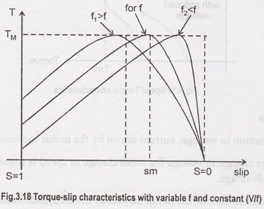
Supply frequency control to control Ns called v/f control
ii.
Supply voltage control
iii.
Controlling number of stator poles to control Ns
iv.
Adding rheostats in stator circuit
Rotor side
i.
Adding external resistance in the rotor circuit.
ii.
Cascade control
iii.
Injecting slip frequency voltage into the rotor circuit
a.
Kramer system
b.
Scherbius system
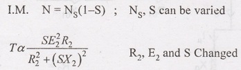
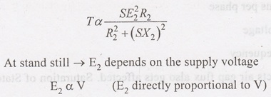
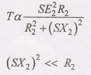
(a) Supply frequency control (or) V/f control

K1
- Stator winding constant
Tph1
- Stator tums per phase
V
- Supply voltage
f-
Supply frequency
f→
Varies that affects air gap flux also gets affected. Saturation of Stator and
rotor
cores.
Hence
it is necessary to maintain air gap flux constant. When supply frequency fs
changed.
V/f→
Constant
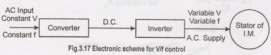
Disadvantages
i.
Supply obtained cannot be used to supply other devices which require constant
voltage. hence an individual scheme for a separate motor is required which
makes it costly.
(b) Supply voltage control
Low
slip region

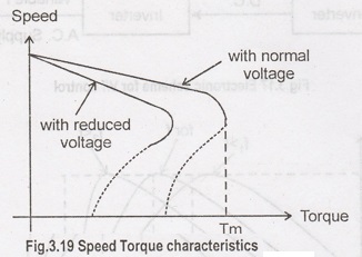
Disadvantages
i.
Reduction in voltage, current drawn by the motor increases.
ii.
Large change in voltage for small change in speed is required is the biggest
disadvantage.
iii.
Increase in current, the motor may set overheated, additional voltage changing
equipment is necessary.
iv.
Hence this method is rarely used in practice.
This
method is used like motors driving fan type of loads.
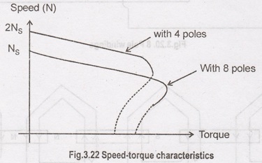
(c)Controlling
Number of poles :
It
is possible to have one, two (or) four speeds control steps by changing the no.
of stator poles.
Disadvantages
A
continuous smooth speed control is not possible by this method.
1.
Consequent poles method
2.
Multiple stator winding method
3.
Pole amplitude Modulation method
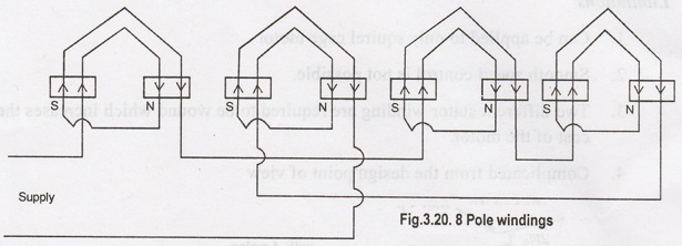
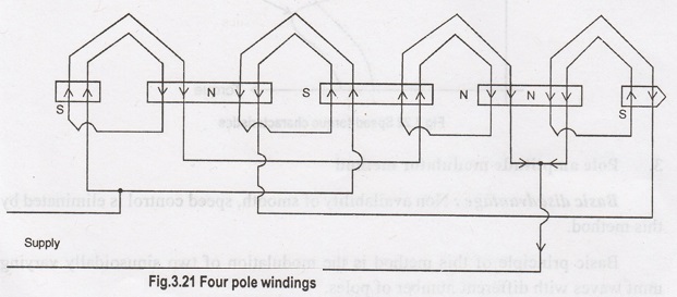
For,
P = 8, f = 50 Hz, → NS = 750 rpm
For,
P = 4, f = 50 Hz, → NS = 1500 rpm
Disadvantages
Speed
change is in step and smooth speed control is not possible. Similarly the
method can be used only for the squired cage type motor as squired cage rotor
adjusts itself to same no. of poles as stator which is not the case in slipning
Induction motor.
(c) Multiple Stator winding method
Limitations
1.
Can be applied to only squirrel cage motor
2.
Smooth speed control is not possible.
3.
Two different stator windings are required to be wound which increases the cost
of the motor.
4.
Complicated from the design point of view
3.
Pole amplitude modulator method
Basic disadvantage:
Non availability of smooth, speed control is eliminated by this method.
Basic
principle of this method is the modulation of two sinusoidally varying mmf
waves with different number of poles.
Advantages
i.
Reduces the size to a greater extent and hence cost of machine.
Limitations
i.
It can be used only for squirrel cage motor.
(d) Adding Rheostats in stator circuit
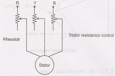
Disadvantages
i.
Large power
ii.
This method is not efficient from speed control point of view hence used as a
stator rather than as a speed control method.
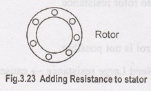
Rotor Circuit

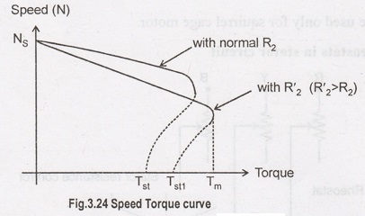
Advantages
i.
R2 ↑, T↓ = but when the load is same
Tst
of motor ↑ α to rotor resistance
Disadvantages
i.
Large speed control is not possible.
ii.
Large speed → Need Large resistance → cause. Large rotor copper loss to reduce
the η.
iii.
This method can not be used for the Squirrel cage I.M.
iv.
The speed above the normal values can not be obtained
v.
Large power losses occur due to large I'R loss
vi.
Sufficient cooling arrangements are required which make the external rheostats
bulky and expensive
vii.
Due to large power losses, n is low
This
method is rarely used in practice.
(a) Rotor Rheostat Control
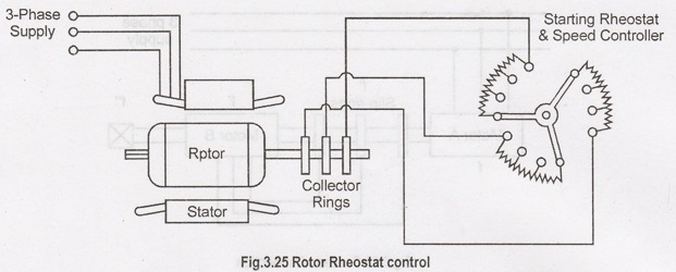
i.
Applicable to slip-ring motors alone.
ii.
Motor speed is reduced by introducing an external resistance in the rotor
circuit.
iii.
This method is in fact, similar to the armature rheostat control method of d.c.
shunt motors.
T
α S/R2
For
a given torque → Slip can be increased i.e. speed can decreased by increasing
the rotor resistance R2.
Serious Disadvantages:
i.
With increase in rotor resistance, I2R losses also increase which
decrease the operating η (efficiency) of the motor. Loss is a directly
proportional to the reduction in the speed.
ii.
Double dependence of speed - not only on R2 but on load as well.
iii.
Due to above disadvantages, it is used where speed changes are needed for short
periods only.
(b) Cascade (or) Concatenation (or)
Tandem operation
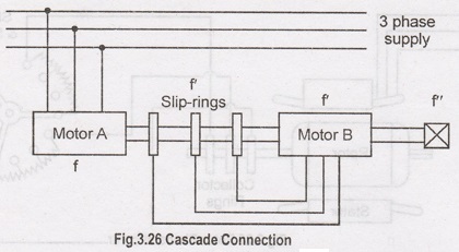
Two
motors are ordinarily mounted on the same shaft (or) both run at the same
speed.
Stator
winding of the main motor 'A' is connected to the mains, while that of the
auxiliary motor 'B' is fed from the rotor circuit of motor 'A'.
Main
motor 'A' should be phase wound (a) slipring type with stator to rotor winding
ratio of 1:1, so each motor may be run from the supply mains separately.
3
ways (some times four ways) to run the Induction motor.
1.
Main motor 'A' may be run separately from the supply.
In
this case Nsa =120 f / Pa, Pa = No. of stator
poles of motor A
2.
Auxiliary motor B may be run separately from the mains (with motor A being
disconnected)
In
this case
Nsb
= 12f/Pb , Pb = No. of stator poles of motor B
3.
The combination may be commulative, such a way that the phase rotation of the
stator fields of both motors is in the same direction.
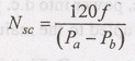
The
synchronous speed of the cascaded set
Nsc
= 120 f / (Pa+ Pb)
Differential cascade
In
this method, the phase rotation of stator field of the motor B is opposite to
30 that of the stator of motor A. This reversal of phase rotation of stator of
motor B is obtained by interchanging any of its two leads.
This
method is rarely used.
The
above expression for synchronous speed becomes meaningless for Pa =
Pb
(c) Injecting an e.m.f. in the
Rotor circuit
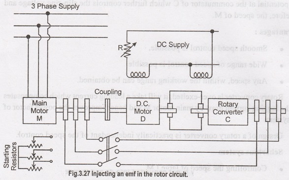
i.
The speed of an induction motor is controlled by injecting a voltage in the
rotor circuit.
ii.
The injected voltage to have the same frequency as the slip frequency.
iii.
When we insert a voltage which is in phase opposition to the induced rotor
e.m.f. it amounts to increase the rotor resistance.
iv.
Inserting a voltage which is in phase with the induced rotor emf is equivalent
to decreasing its resistance.
v.
Speed control using Kramer system, used in the case of large motors of 4000 kW
(or) more. (steel rolling mills, large induction motors).
Rotary converter
- Converts the low slip frequency a.c. power into d.c. power, which is used to
drive a d.c. shunt motor 'D' mechanically coupled to the main motor 'M'.
Main
motor is coupled to the shaft of the d.c. shunt motor D. The slip-rings of M
are connected to those of the notary converter C. The d.c. output of C is used
to drive D. Both C and D are excited from the d.c. bus-bars (or) from an
exciter.
There
is a field regulator which governs the back emf of E, of D and hence the d.c.
potential at the commutator of C which further controls the slip-ring voltage
and therefore, the speed of M.
Advantages:
i.
Smooth speed control is possible.
ii.
Wide range of speed control is possible.
iii.
Any speed, within the working range can be obtained.
Rotary
converter is over-excited, it will take a leading current which compensates for
the lagging current draw by main motor M and hence improves the power factor of
the system.
Design
of a rotary converter is practically independent of the speed control.
(d) Scherbius system
i.
Controlling the speed of large I.M.
ii.
The slip energy is not converted into dc and then fed to a d.c. motor, rather
it is fed directly to a special 3-phase (or 6-phase) a.c. commutator motor is
called a scherbius machine.
iii.
The poly Phase winding of machine C is supplied with the low-frequency output
of machine M through a regulating Transformer (RT).
iv.
The commutator motor C is a variable-speed motor and its speed (and hence that
of M) is controlled by either varying the tappings on RT (or) by adjusting the
position of brushes on C.
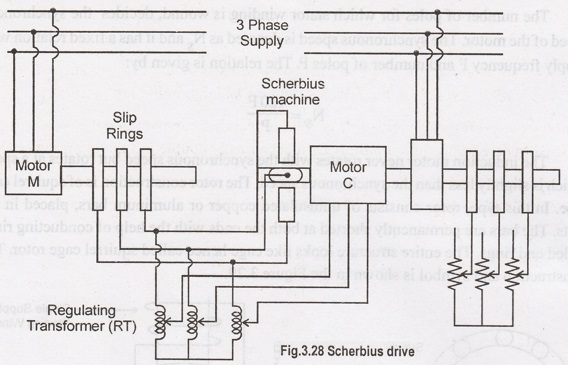
Disadvantages:
Used
only for slipring induction motor.
Electrical and Instrumentation Engineering: Unit III: AC Rotating Machines : Tag: : Methods of speed control | AC Rotating Machines - Speed Control of Three Phase Induction Motor
Related Topics
Related Subjects

Electrical and Instrumentation Engineering
BE3254 - 2nd Semester - ECE Dept - 2021 Regulation | 2nd Semester ECE Dept 2021 Regulation