Electrical and Instrumentation Engineering: Unit II: DC Machines
Principle of Operation for Generating
DC Machines
Let us consider a single turn coil ABCD rotated on a shaft within a uniform magnetic field of flux density. It is rotated in an anticlockwise direction.
PRINCIPLE OF OPERATION FOR GENERATING
Let
us consider a single turn coil ABCD rotated on a shaft within a uniform
magnetic field of flux density. It is rotated in an anticlockwise direction.


Let
'l' be the length and 'b' be the breadth of the coil in metres.
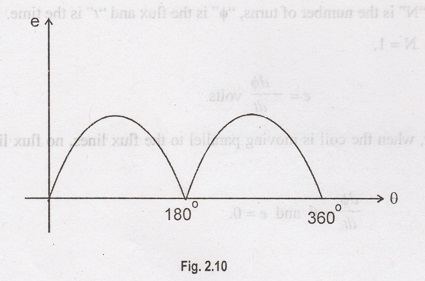
When the coil sides AB and CD are moving parallel to the magnetic field, the
flux lines are not being cut and no emf is induced in the coil. At this
position, we assume the angle of rotation 'θ' as zero.
This
vertical position of the coil is the starting position. According to Faraday's
law II, the emf induced is proportional to the rate of flux linkages.

where,
"N" is the number of turns, "φ" is the flux and "t"
is the time.
As
N = 1,

Initially,
when the coil is moving parallel to the flux lines, no flux line is cut and
hence,


During
the first half revolution, current flows along ABLMCD through brush B1
which is positive and into B2 (negative brush). After half cycle AB
and CD have exchanged positions along with the segments P and Q and current now
flows, through DCLMBA. B2 is now in contact with QCB, continues to
be +ve.
For
each half revolution, the position of position of segments P and Q also
reverse. Hence the current in the load is always unidirectional. The change
over the segments P and Q takes place when flux linkage (or) induced emf is
minimum. In a generator, the split-rings are called commutator.
Electrical and Instrumentation Engineering: Unit II: DC Machines : Tag: : DC Machines - Principle of Operation for Generating
Related Topics
Related Subjects

Electrical and Instrumentation Engineering
BE3254 - 2nd Semester - ECE Dept - 2021 Regulation | 2nd Semester ECE Dept 2021 Regulation