Electrical and Instrumentation Engineering: Unit III: AC Rotating Machines
Equivalent Circuit of Induction Motor
AC Rotating Machines
The three phase induction motor is generally treated as a rotating transformer. The transformer has two winding - one is primary and another one secondary winding.
EQUIVALENT CIRCUIT OF INDUCTION MOTOR
The
three phase induction motor is generally treated as a rotating transformer. The
transformer has two winding - one is primary and another one secondary winding.
Similarly in an induction motor, stator acts as primary and rotor acts as
rotating secondary (or short circuited).
Hence
the transfer of energy from stator to rotor in an induction motor takes place
entirely inductively linking the two. How an induction motor takes place
entirely inductively linking the two. How an induction motor takes can
represented as a transformer.
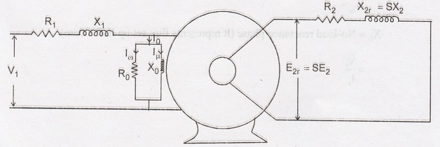
Fig 3.11
Let
V1
= Supply voltage per phase (it produces the flux which line with stator and
rotor)
E1
= The induced emf in stator/phase due to self induction
E2
= The induced emf in the rotor due to mutual induction at standstill
R1
= Stator resistance/phase
X1
= Stator resistance/phase
R2
= Rotor resistance/phase
X2r
= Rotor resistance/phase in running condition (sX2)
E2r
= Rotor induced emf in running condition/phase (sE2).
When
the induction motor operates under no load condition, if draws some current
from the supply. It is to produce flux is in the air gap and to supply iron
losses. Normally the no load current consist of two components IW Iµ,

Where
IW
= Working Component which supplies no load losses.
Iµ
= Magnetizing Component which sets up flux.
R0
= No-load resistance/phase (It represents no load losses) = V1 / IW
X0
= No-load reactance/phase (It represents flux set up in the core) =V1
/ Iµ
Equivalent Circuit of an Induction Motor


When the induction motor load changes, the
motor speed also changes. Correspondings slip also changes. Due to this
reactance X2r changes. So it is indicated as a variable element.
Equivalent Circuit of the Rotor
The
rotor current under running condition:

from
this equation rotor circuit consists of a fixed reactance X2 in
series with a variable resistance R2/S and supplied with fixed
voltage E2.

Now,
the variable resistance can be written as:

Now,
the variable resistance R2/S consists of two parts R2, R2
(1-S)/S
(i)
The part R2 is rotor resistance itself, which represents that part
when rotor copper loss takes place.
(ii)
The part R2(1-S)/S represents load resistance RC.
So
it is indicate as an electrical equivalent of the mechanical load on the motor.
Equivalent of the mechanical load on the motor.
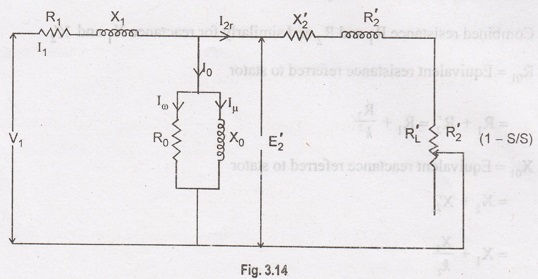
Equivalent Circuit Referred to Stator
K
= transformation ratio =E2/E1
Rotor
parameters are transferred to stator
E2'
= E2/K.
Rotor
current referred to stator:

Rotor
reactance referred to stator (X2)
X2'
= X2/K2
Rotor
resistance referred to stator (R2')
R2'
= R2/K2
Load
resistance RL referred to stator:

Equivalent
circuit referred to stator.
Approximate Equivalent Circuit
The
exciting circuit consists of R0 and x0 this existing
circuit is transformed to the left of R1 and X1, the in
accuracy involved due to this is negligible. Hence the calculation are very
simple this is known as approximate equivalent circuit

Fig 3.15
Now
the circuit is further simplified.
Combined
resistance R1 and R2 and similarly for reactance X1
and X2'
R01
= Equivalent resistance referred to stator = R1 + R2' = R1
+ (R2/k2)
X01
= Equivalent reactance referred to stator = X1 + X2' = X1
+ (X2/k2)

The
equivalent circuit (referred to stator).


Electrical and Instrumentation Engineering: Unit III: AC Rotating Machines : Tag: : AC Rotating Machines - Equivalent Circuit of Induction Motor
Related Topics
Related Subjects

Electrical and Instrumentation Engineering
BE3254 - 2nd Semester - ECE Dept - 2021 Regulation | 2nd Semester ECE Dept 2021 Regulation