Electrical and Instrumentation Engineering: Unit III: AC Rotating Machines
Equation of Induced EMF in Alternator
Derivation of Equation of induced emf
EQUATION OF INDUCED EMF
Let,
Zph
= number of conductors or coils sides in series/phase
Zph
= 2Tph, where Tp is the number of coils or turns per
phase
P
= number of poles
f
= frequency of induced emf in Hz
φ
= flux/pole in webers
Kc
or Kp = pitch factor or coil span factor = cos (α/2)
Kf
= form factor = 1.11 (If e.m.f is assumed sinusoidal)
N
= rotor speed in r.p.m.
For
one revolution of the rotor, each stator conductor is cut by a flux of φP
webers
dφ
= φР
dt
= 60/N Second.
Average
emf induced per conductor = dφ/dt = φР / (60/N) = φΡΝ / 60
We
know that f = PN / 120 (or) N = 120f / P
Substituting
this value of N, we get average emf per conductor as

If
there are Zph conductors in series/phase, then
Average
e.m.f / Phase = 2fφ Zph volts = 4fφ Tph volts
RMS
value of e.m.f / Phase = 1.11 × 4fφ Tph = 4.44fφ Tph
Volts.
The
above equation is true only if the winding concentrated in one slot. But
practically it is not true, as the winding for each phase under each pole is
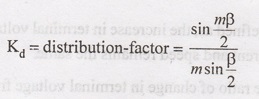
distributed and for such cases kp and kd must be
considered.
Actually
available voltage/phase = 4.44 kp kd fφ Tph
Volts
Kp
kd = kw = winding factor.
If
the alternator is star connected, then the line voltage is √3 times the phase
voltage.
Electrical and Instrumentation Engineering: Unit III: AC Rotating Machines : Tag: : - Equation of Induced EMF in Alternator
Related Topics
Related Subjects

Electrical and Instrumentation Engineering
BE3254 - 2nd Semester - ECE Dept - 2021 Regulation | 2nd Semester ECE Dept 2021 Regulation