Electronic Devices and Circuits: Unit IV: Feedback Amplifiers and Oscillators
Crystal Oscillators
Quartz Crystal Construction, Advantages
The crystal is a thin slice of Piezo-electric material, such as quartz, tourmaline and rochelle salt, which exhibit a property called Piezo-electric effect. The Piezo electric effect represents the chracteristics that the crystal reacts to any mechanical stress by producing an electric charge. In the reverse effect, an electric field results in mechanical strain.
CRYSTAL OSCILLATORS
Fig.
4.17 shows a crystal controlled oscillator circuit. Here it is a Colpitt's
crystal oscillator in which the inductor is replaced by the crystal. In this
type a Piezo-electric crystal, usually quartz is used as a resonant circuit
replacing an LC circuit.
The
crystal is a thin slice of Piezo-electric material, such as quartz, tourmaline
and rochelle salt, which exhibit a property called Piezo-electric effect.
The
Piezo electric effect represents the chracteristics that the crystal reacts to
any mechanical stress by producing an electric charge. In the reverse effect,
an electric field results in mechanical strain.

Quartz Crystal Construction
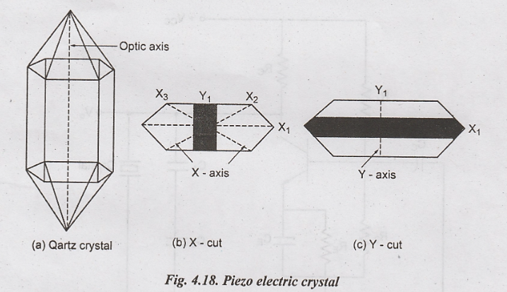
In order to obtain high degree of frequency stability, crystal oscillators are essentially used. Generally, the crystal is a ground wafer of translucent quartz or tourmaline stone placed between two metal plates and housed in a stamp sized package. There are two different methods of cutting this crystal wafer from the crude quartz. The method of cutting determines the natural resonant frequency and temperature coefficient of crystal. When the wafer is cut in such a way that is flat surfaces are perpendicular to its electrical axis (x-axis), it is called an x-cut crystals as shown in Fig. 4.18 (b) when the wafer is cut in such a way that its flat surfaces are perpendicular to its mechanical axis (y-axis), it is called y-cut crystal as shown in Fig. 4.18 (c).
If
an alternating voltage is applied, then the crystal wafer is set into
vibration. The frequency of vibration equal to the resonant frequency of the
crystal is determined by its structural characteristics. If the frequency of the
applied ac voltage is equal to the natural resonant frequency of the crystal
then the maximum amplitude of vibration will be obtained.
In
general, the frequency of vibration is inversely proportional to the thickness
of the crystal.
The
frequency of vibration is 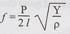
Where
Y - young modulus
ρ
- density of the material
and
P - 1, 2, 3, ...
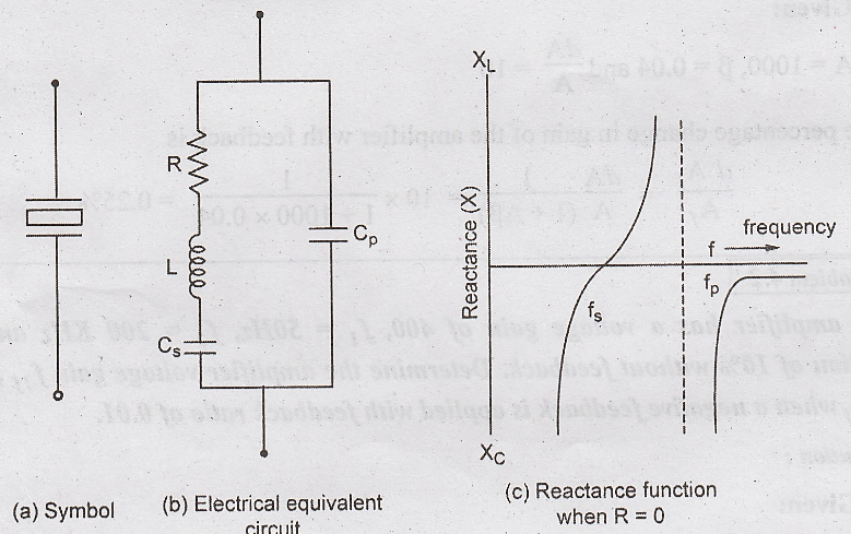
The
crystal is suitably cut and polished to vibrate at a certain frequency and
mounted between two metal plates as shown in Fig.4.19 (a)
The
equivalent circuit of the crystal is shown in Fig. 4.19 (b)
The
ratio of Cp to CS may be several hundred or more so that
series resonance frequency is very close to parallel resonant frequency. The
resonant frequency is inversely proportional to the thickness of the crystal.
Resonant
frequencies from 0.5 to 30 MHz can be obtained.
The
reactance function shown in Fig. 4.19 (c)
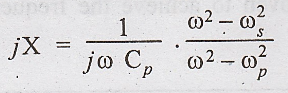
Neglecting
R, here 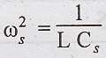 is the series resonant frequency and
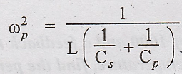 is the parallel resonant frequency
Since
CP >> CS, 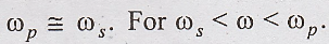 The reactance is inductive and
for ω out of the above range, it is capacitive.
The reactance is inductive and
for ω out of the above range, it is capacitive.
For
crystal Hartley oscillator the capacitors C1 and C2 shown
in in Fig. 4.17 are replaced with inductors L1 and L2
respectively. So that the reactance is capacitive, hence its oscillation
frequency is 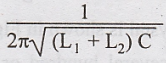
Advantages
The
advantages of the crystal is its very high Q as a resonant circuit, which
results in good frequency stability for the oscillator. However since the
resonance frequencies of the crystals are temperature dependent, it is
necessary to enclose the crystal in a temperature controlled oven to achieve
the frequency stability of the order of 1 part in 1010.
Electronic Devices and Circuits: Unit IV: Feedback Amplifiers and Oscillators : Tag: : Quartz Crystal Construction, Advantages - Crystal Oscillators
Related Topics
Related Subjects

Electronic Devices and Circuits
EC3353 - EDC - 3rd Semester - ECE Dept - 2021 Regulation | 3rd Semester ECE Dept 2021 Regulation