Electrical and Instrumentation Engineering: Unit III: AC Rotating Machines
Construction of Alternator
AC Rotating Machines
An alternator has 3-phase winding on the stator and a d.c field winding on the rotor.
CONSTRUCTION OF ALTERNATOR
An
alternator has 3-phase winding on the stator and a d.c field winding on the
rotor.
1. Stator:
It
is the stationary part of the machine and is built up of sheet-steel
laminations having slots on its inner periphery. A 3-phase winding is placed in
these slots and serves as the armature winding of the alternator. The
alternator winding is always connected in star and the neutral is connected to
ground.
2. Rotor:
The
rotor carries a field winding which is supplied with direct current through two
slip rings by a separate d.c source. Rotor construction is of two types,
namely,
1.
Salient (or) Projecting Pole Type
2.
Non-Salient Pole (or) Cylindrical Type.
(i) Salient Pole Type:
The
rotor of this type is used almost entirely for slow and moderate speed
alternators, since it is least expensive and provides sample space for the
field ampere-turns. Salient poles cannot be employed in high speed generators
on account of very high peripheral speed and the difficulty of obtaining
sufficient mechanical strength.
The
rotor of this type is used almost entirely for slow and moderate speed
alternators, since it is least expensive and provides sample space for the
field armatures. Salient poles cannot be employed in high speed generators on
account of very high peripheral speed and the difficulty of obtaining sufficient
mechanical strength.

The
salient poles are made of thick steel laminations riveted together and are
fixed to rotor by a dove-tail joint. The pole faces are usually provided with
slots for damper windings. These dampers are useful in preventing the hunting.
The pole faces are so shaped that the radial air gap length increase from the
pole centre to the pole tips. So that the flux distribution over the armature
is sinusoidal and waveform of generated e.m.f is sinusoidal. The field coils
are placed on he pole-pieces and connected in series. The ends of the field
windings are connected to a d.c source through slip-rings carrying brushes and
mounted on the shaft of the field structure.
The
salient-pole field structure has the following special features.
(i)
They have large diameter and short axial length.
(ii)
The pole shoes cover about 2/3 of pole pitch.
(iii)
Poles are laminated in order to reduce eddy current losses.
(iv)
They are employed with hydraulic turbine and diesel engines.
The
speed is from 120 to 400 r.p.m.
(ii) Smooth Cylindrical or
Non-Salient Pole Type:
The rotors of this type are used in very high speed alternators driven by steam turbines. To reduce the peripheral velocity, the diameter of the rotor is reduced and axial length is increased. Such rotors have two or four poles.
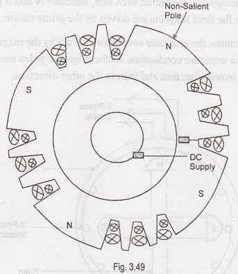
It
consists of a cylindrical steel forging which is suitably fabricated
mechanically and treated thermally. The forging has radial slots in which the
field copper, usually in strip form is placed. The coils are held in place by
steel or bronze wedges and the coil ends are fastened by metal rings. The slots
over certain portions of the core are omitted to form pole faces. The region
forming the poles are usually left unslotted as shown in Figure 3.49.
The
non-salient pole field structure has the following:
Special Features:
(i)
They are of small diameter and of very long axial length.
(ii)
Less windage loss.
(iii)
The speed employed is from 1,000 to 3,000 rpm.
(iv)
Better in dynamic balancing and quieter in operation.
Alternator
Working Principle:
The
field magnets are magnetized by applying 125 volts or 250 volts through slip rings.
The field windings are connected such that, alternate N and S poles are
produced. The rotor and hence the field magnets are driven by the prime mover.
As
the rotor rotates, the armature conductors are cut by the magnetic flux. Hence
an emf is induced in the armature conductors. As the magnetic poles are
alternately N and S poles, this emf acts in one direction and then in the other
direction.

Hence
an alternating emfis induced in the stator conductors. The frequency of induced
emf depends on the number N and S poles moving past an armature conductor in
one second. The direction of induced emf can be found by Fleming's right hand
rule and frequency is given by
f
= PN /120
where
N
= Speed of rotor in r.p.m and
P
= Number of rotor poles.
Electrical and Instrumentation Engineering: Unit III: AC Rotating Machines : Tag: : AC Rotating Machines - Construction of Alternator
Related Topics
Related Subjects

Electrical and Instrumentation Engineering
BE3254 - 2nd Semester - ECE Dept - 2021 Regulation | 2nd Semester ECE Dept 2021 Regulation