Electrical and Instrumentation Engineering: Unit III: AC Rotating Machines
Concept of Rotating Magnetic Field
Induction Motor
If an balanced 3 phase voltage is applied to a balanced 3 phase winding, it produces rotating magnetic field of constant amplitude.
CONCEPT OF ROTATING MAGNETIC FIELD
If
an balanced 3 phase voltage is applied to a balanced 3 phase winding, it
produces rotating magnetic field of constant amplitude.
The
speed of the rotating magnetic field is given by:
NS
= 120f / P
where,
f
is the frequency of the supply.
n
is the number of stator poles.
The
stator of synchronous and induction motor may be star (or) delta connected. The
three phase windings are displaced from each other by an angle 120°.
The
current through the three phase windings are displaced from each other by an
angle of 120° electrical. The expression for instantaneous values of three
three flux are given by:


Let
us consider the following cases:
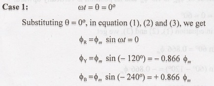

Case 1: Phasor Addition of Fluxes
The
Figure 3.7 shows the phasor addition of the above three fluxes from the figure,
we
get

Therefore,
the magnitude of φRes is 1.5 m and its position is vertically
upward.


Case 2: Phasor Addition of Flux
Figure
3.8 shows the phasor addition of the above three flux, from the figure, we get

Therefore,
the magnitude of φRes is 1.5 φm and it is rotated through
60° in space in clockwise direction compared to its previous position in case
1.
Case 3:
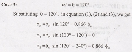

Figure
3.9 shows the phasor diagram addition of the above three flux, we get,

Therefore,
the magnitude of φRes is 1.5 φm and its rotated through
120° in space in clockwise direction compared to its previous position in case
1.
Case 4:


Figure
3.10 shows the phasor addition of the above three fluxes, from the figure, we
get

Therefore,
the magnitude of φRes is 1.5 φm and its is rotated
through 180° space in clockwise direction compared to its previous in case 1.
Electrical and Instrumentation Engineering: Unit III: AC Rotating Machines : Tag: : Induction Motor - Concept of Rotating Magnetic Field
Related Topics
Related Subjects

Electrical and Instrumentation Engineering
BE3254 - 2nd Semester - ECE Dept - 2021 Regulation | 2nd Semester ECE Dept 2021 Regulation