Electronic Devices and Circuits: Unit IV: Feedback Amplifiers and Oscillators
Colpits Oscillator
Analysis
Introduction and Details of Colpits Oscillator
COLPITS OSCILLATOR
The
Colpitts oscillator shown in Fig. 4.14.
Z1
and Z2 are capacitors and Z3 is an inductor. The
resistors R1, R2 and RE provide the necessary
dc bias to the transistor CE is a bypass capacitor. CC1 and CC2
are coupling capacitors. The feedback network consisting of capacitors C1
and C2 and an inductor L determines the frequency of oscillation.
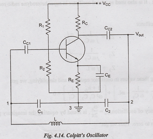
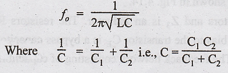
When the supply voltage + VCC is switched ON, a transient current is produced in the tank circuit and consequently, damped harmonic oscillations are setup in the circuit. The oscillatory current in the tank circuit produces ac voltage across C1 and C2. As terminal 3 is earthed, it will be at zero potential. If terminal 1 is at a positive potential with respect to 3 at any instant, terminal 2 will be at a negative potential with respect to 3 at the same instant. Thus the phase difference between terminals, 1 and 2 is always 180°. In the CE mode, the transistor provides the phase difference of 180° between the input and output. Therefore the total phase shift is 360°. Thus at the frequency determined for the tank circuit, the necessary condition for sustained oscillations is satisfied. If the feedback is adjusted so that the loop gain Aβ = 1, the circuit acts as an oscillator. The frequency of oscilation is
It
is widely used in commercial signal generators for frequencies between 1 MHz
and 500 MHz. It is also used as a local oscillator in super heterodyne radio
receiver.
Analysis
For
this oscillator
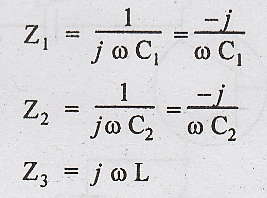
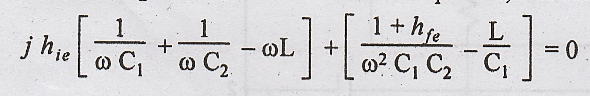
Substituting
these values in oscillator equation, and simplifying, we get
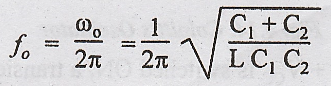
The
frequency of oscillation, fo = ωo/2π, is found by
equating the imaginary part of above equation to zero. Thus we get
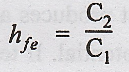
Substituting
this value and simplifying, we get
Electronic Devices and Circuits: Unit IV: Feedback Amplifiers and Oscillators : Tag: : Analysis - Colpits Oscillator
Related Topics
Related Subjects

Electronic Devices and Circuits
EC3353 - EDC - 3rd Semester - ECE Dept - 2021 Regulation | 3rd Semester ECE Dept 2021 Regulation