Electronic Devices and Circuits: Unit III: Multistage Amplifiers and Differential Amplifier
Tuned Amplifiers
Parallel Resonant Circuit
An amplifier which amplifies a specific frequency is called tuned voltage amplifier or tuned amplifier. In situations, when the receiver is required to pick up and amplify the desired radio frequency signal and reject the other frequencies, tuned amplifiers are used.
TUNED AMPLIFIERS
An
amplifier which amplifies a specific frequency is called tuned voltage
amplifier or tuned amplifier.
Need for Tuned Amplifiers
In
situations, when the receiver is required to pick up and amplify the desired
radio frequency signal and reject the other frequencies, tuned amplifiers are
used.
For
example, in radio and television stations, for transmitting at a particular
radio frequency, we are using tuned amplifier.
The
use of tuned circuit makes the selection and amplification of a particular
desired radio frequency possible.
Thus
the tuned amplifiers should do the following functions.
i.
Selection of a desired radio frequency signal
ii.
Amplification of the selected signal to a suitable voltage level.
Types of Tuned Amplifiers
The
tuned amplifiers are classified as
i.
Small signal tuned amplifiers
ii.
Large signal tuned amplifiers
Small Signal Tuned Amplifier
This
is used for amplifying small signals at radio frequencies.
The
small signals have very small power and. They are operated in class A
amplifiers to minimize distortion.
Large Signal Tuned Amplifiers
These
amplifiers amplify the large signals at radio frequencies. The large signals
have large amount of power, hence they are operated in class AB, B or C
amplifiers.
The circuit efficiency will be high and it eliminates harmonic distortion.
PARALLEL RESONANT CIRCUIT
The
parallel resonant circuit consists of an inductor (L) and a capacitor (C)
connected in parallel to each other Fig. 3.26 shows the parallel resonant
circuit connected across ac voltage source. R denotes the coil resistance, in
the order of few ohms.

Let
the frequency of the ac supply source is varied, then the circuit will have
different impedance at different frequencies.
When
the frequency is increased, the inductive reactance (XL) is also
increased and the capacitive reactance (XC) is decreased.
At
a certain frequency, the inductive reactance is equal to the capacitive
reactance. This frequency is called resonance frequency, denoted by fo.
At
resonance, the impedance of the circuit becomes maximum and the current is
minimum.
At
resonance,


Resonant
frequency, fo is expressed in Hertz.
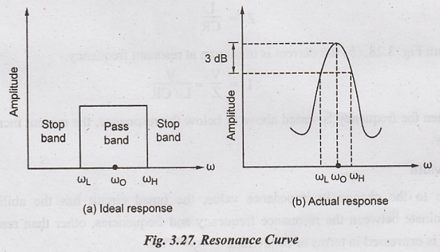
Resonance Curve
The
response of tuned amplifier is maximum at resonance frequency. The tuned
amplifier is designed to reject all frequencies below the lower cut off
frequency fL and above the upper cut-off frequency fH
At
frequency
f
= fo, tuned circuit - resistive load (reactance = 0 i.e., V & I
are in phase)
f
> fo, Circuit becomes capacitive (current leads the applied
voltage)
f
< fo, Circuit becomes inductive (current lags the applied
voltage)
Impedance
Fig.
3.28 shows the variation of circuit impedance with the change in frequency of
applied voltage. The impedance value is maximum at resonance.
When
the frequency is varied above or below resonance, the impedance value is
decreased.
The
gain is directly proportional to the value of its load impedance. Thus tuned
amplifiers are used for amplifying narrow band of frequencies.
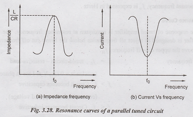
The
impedance value is maximum at resonance, and is given by
Z
= L/CR
From
Fig. 3.28, (b) the current is minimum at resonant frequency.
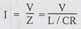
When
the frequency is varied above or below the resonance, the current increases rapidly.
Bandwidth
Due to the change in impedance value, the tuned circuit has the ability to discriminate between the resonance frequency and frequencies, other than resonant circuit is expressed in terms of bandwidth.
Bandwidth
of a tuned circuit is defined as the band of frequencies between the points in
the resonance curve. When the impedance drops to 1/√2 or 0.707 of its maximum
value at resonance.


The
points A and B are called as half-power points as the power at these points is
half the power developed at resonance.
f1
- lower half-power frequency
f2
- upper half-power frequency
Q-Factor
For
better selectively, the resonance curve should be very sharp, i.e., impedance
should be decreased rapidly if the frequency is varied above and below the
resonant frequency.
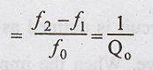
Selectivity
or sharpness of a resonant circuit is defined as the ratio of the bandwidth of
the circuit to its resonant frequency. It is otherwise represented using
quality factor or Q-factor.
Sharpness = Bandwidth/Resonant Frequency
Where
QO is Q factor, defined as the ratio of inductive reactance at
resonance to the circuit resistance.

QO
depends upon the coil resistance R.
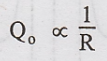
The
circuit with smaller R, has higher QO.

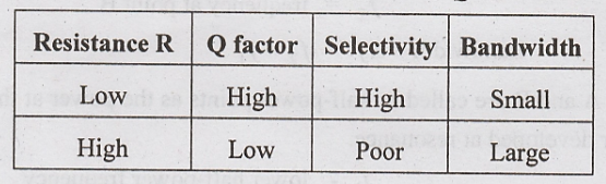
Table
3.1. Summary on relation between Q and BW
Electronic Devices and Circuits: Unit III: Multistage Amplifiers and Differential Amplifier : Tag: : Parallel Resonant Circuit - Tuned Amplifiers
Related Topics
Related Subjects

Electronic Devices and Circuits
EC3353 - EDC - 3rd Semester - ECE Dept - 2021 Regulation | 3rd Semester ECE Dept 2021 Regulation