Electrical and Instrumentation Engineering: Unit IV: Measurements and Instrumentation
Three Phase Power Measurement
Methods
In ac circuits, power is measured with the help of wattmeter. A wattmeter is an instrument, which consists of two coils called the potential coil (PC) and the current coil (CC).
THREE PHASE POWER MEASUREMENT
In
ac circuits, power is measured with the help of wattmeter. A wattmeter is an
instrument, which consists of two coils called the potential coil (PC) and the
current coil (CC).
The
potential coil having high resistance is connected across the load and carries
the current proportional to the potential difference across the load. The
current coil having low resistance is connected in series with the load.
The
three phase power measurement can be
carried out using the following methods:
i.
One wattmeter method
ii.
Two wattmeter methods
iii.
Three wattmeter method.
One Wattmeter Method
In
a balanced 3-wire, 3-phase load circuit the power in each phase is equal and,
therefore, the total power of the circuit can be determined by multiplying the
power measured in any one phase. Hence, the power measurement in three-phase,
three-wire circuits can be carried out by using the one wattmeter only.
But
this method has a disadvantage. Even a
slight degree of unbalance in the loading produces a significant error in the
measurement.
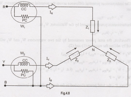
Two Wattmeter Method
Two Wattmeter
Method can be employed to measure the power in a 3 phase, three- wire star or
delta connected the balanced or unbalanced load.
In
two wattmeter method, the current coils of the wattmeter are connected with any
two lines, say R and Y and the potential coil of each wattmeter is joined on
the same line, the third line i.e. B as shown below in figure 4.8
The power measurement in
three-phase, three-wire load circuits usually carried out using this method.
The
current coils of two wattmeters are inserted in any two lines, and the
potential coil is connected from its own current coil to the line without the
current coil.
It
can be proved that the sum of the power measured by two wattmeter W1
and W2 is equal to the total instantaneous power absorbed by the load.
But in actual practice, wattmeters read the average power because of the
inertia of their moving system.
The
two wattmeter method of power measurement in three-phase circuits is suitable
for every type of three-phase circuit weather circuit is balanced or unbalanced
and star connected or delta connected.
1. Measurement of Power by Two
Wattmeter Method in Star Connection
Considering
the above figure (4.8) in which Two Wattmeter W, and W2 are connected, the
instantaneous current through the current coil of Wattmeter, W, is given by the
equation shown below:
W1
= iR
The
instantaneous potential difference across the potential coil of Wattmeter, W1
is given as:
W1
= eRN – eBN
Instantaneous
power measured by the Wattmeter, W1 is
W1
= iR (eRN – eBN) ………………. (1)
The
instantaneous current through the current coil of Wattmeter, W2 is
given by the equation:
W2
= iY
The
instantaneous potential difference across the potential coil of Wattmeter, W2
is given as:
W2
= eYN – eBN
Instantaneous
power measured by the Wattmeter, W2 is:
W2
= iY (eYN – eBN) ………………. (2)
Therefore,
the total power measured by the two wattmeters W1 and W2
will be obtained by adding the equation (1) and (2).
W1
+ W2 = iR (eRN - eBN) + iY
(eYN - eBN)
W1
+ W2 = iR eRN + iY eYN -
eBN (iR + iY) or
W1
+ W2 = iR eRN + iY eYN +
iB eBN (i.e. iR + iY +iB
= 0)
W1
+ W2 = P
Where,
P- the total power absorbed in the three loads at any instant.
2. Measurement of Power by Two
Wattmeter Method in Delta Connection
Considering
the delta connected circuit shown in the figure 4.9
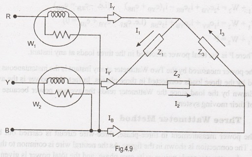
The
instantaneous current through the coil of the wattmeter, W1 is given
by the equation:
W1
= iR = i1 – i3
Instantaneous
power measured by the Wattmeter, W1 will be:
W1
= eRB
Therefore,
the instantaneous power measured by the wattmeter, W1 will be given
as:
W1
= eRB (i1 – i3) ………………. (3)
The
instantaneous current through the coil of the wattmeter, W2 is given
by the equation:
W2
= iY = i2 – i1
The
instantaneous potential difference across the potential coil of wattmeter, W2
:
W2
= eYB
Therefore,
the instantaneous power measured by the wattmeter, W2 will be :
W2
= eYB (i2 – i1) ………………. (3)
Hence,
to obtain the total power measured by the two wattmeter the two equations, i.e.
equation (3) and (4) has to be added.
W1
+ W2 = eRB (i1 – i3) + eYB
(i2 – i1)
W1
+ W2 = i1 eRB + i1 eYB –
i3 eRB – i1 eYB
W1
+ W2 = i2 eYB + i3 eBR –
i1 (eYB + eBR) (i.e. –eRB = eRB
)
W1
+ W2 = i1 eRY + i2 eYB +
i3 eBR (i.e. eRY + eYB + eBR
= 0)
W1
+ W2 = P
Where,
P- the total power absorbed in the three loads at any instant.
The
power measured by the Two Wattmeter at any instant is the instantaneous power
absorbed by the three loads connected in three phases. In fact, this power is
the average power drawn by the load since the Wattmeter reads the average power
because of the inertia of their moving system.
Three Wattmeter Method
The
power measurement in three-phase, three-wire circuit is carried out by this
method. The connection is shown in the figure. As the neutral wire is common to
the three phases, each wattmeter reads power in its own phase, and the total
power is given by the sum of the readings of three wattmeters.
Total
power of load circuit, P3- φ
= W1 + W2 + W3
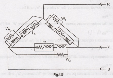
In the case of delta connected circuits, power measurement by three wattmeter method is very difficult because phase coils of load are required to be broken for inserting the current coils of wattmeter.
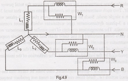
Three-phase Wattmeter
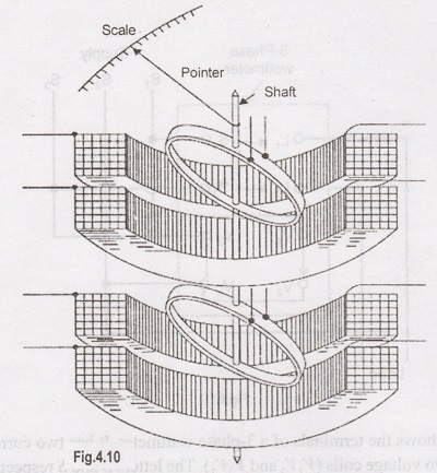
Two
single phase wattmeters are required to measure the total power taken by a 3-
phase circuit. Two such wattmeters may be combined into one so that total
3-phase power is read from a single scale. Such an arrangement gives rise to a
3-phase wattmeter. Fig. 4.11 shows a 3-phase dynamometer type wattmeter which
is most commonly used in polyphase circuits. The arrangement consists of two
similar dynamometer wattmeters; the two voltage coils being mounted on the same
shaft and rotate in their respective current coils. The wattmeter elements are
connected according to two-wattmeter method and the resulting deflection of the
instrument pointer is a function of the algebraic summation of the torques
produced by the individual element. The deflection of the instrument pointer is
therefore a function of the total power.
In
the design of such a 3-phase wattmeter, care must be taken that the two
elements have no mutual action i.e., field from one element must not produce
torque in the other. This may be checked by exciting the current circuit of one
element and the voltage circuit of the other. There should be no deflection for
this connection. Also the two elements must be matched in characteristics. This
may be checked by connecting the elements with voltage circuits in parallel and
the current circuits in series opposing. Again there should be no deflection.
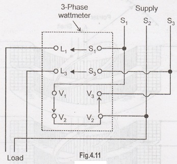
Fig.
4.11 shows the terminals of a 3-phase wattmeter. It has two current coils (L1 S1 and L3 S3) and two
voltage coils (V1 V2
and V2 V3). The
letters L and S respectively stand for load and supply.
Note
that current coils and voltage coils are connected in the two supply lines (S1
and S3 in the present case) of the 3-phase circuit. Observing
polarity is essential in a 3- phase wattmeter because if the instrument is not
connected correctly, it may indicate upscale but incorrectly.
A
convenient rule to follow is to connect the instrument so that, as the current
flows from the supply, it enters both the current and voltage circuits of the
wattmeter at the marked (0 or ±) terminals. Note the arrowheads in the diagram.
The arrowhead between S1 and L1 indicates that positive
direction of current is from S1 to L1. Similarly positive
direction of voltage is from V1 to V2 and from V2
to V3.
Electrical and Instrumentation Engineering: Unit IV: Measurements and Instrumentation : Tag: : Methods - Three Phase Power Measurement
Related Topics
Related Subjects

Electrical and Instrumentation Engineering
BE3254 - 2nd Semester - ECE Dept - 2021 Regulation | 2nd Semester ECE Dept 2021 Regulation