Electronic Devices and Circuits: Unit III: Multistage Amplifiers and Differential Amplifier
Small Signal Tuned Amplifiers
Single Tuned Amplifiers
A number of tuned amplifier stages are connected together in cascade so that large voltage gain can be obtained. These tuned amplifiers are classified as i. Single Tuned Amplifier ii. Double Tuned Amplifier iii. Stagger Tuned Amplifier
SMALL SIGNAL TUNED AMPLIFIERS
A
number of tuned amplifier stages are connected together in cascade so that
large voltage gain can be obtained. These tuned amplifiers are classified as
i. Single Tuned
Amplifier
It
uses only one parallel circuit as the load impedance in each stage.
All
the tuned circuits are tuned to the same frequency.
ii. Double Tuned
Amplifier
It uses two inductively coupled tuned circuits for each stage and all the tuned circuits are tuned to same frequency.
iii. Stagger Tuned
Amplifier
In
this method a number of single tuned stages are connected in cascade.
The
successive tuned circuits are tuned to slightly different frequencies.
SINGLE TUNED AMPLIFIERS
These
amplifiers use only one parallel circuit. With all tuned circuits tuned to the
same frequency. Single tuned amplifiers are of two types.
i.
Capacitance coupled amplifiers
ii.
Inductance coupled amplifiers
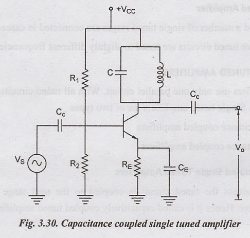
i. Capacitance Coupled
Single Tuned Amplifiers
The
output across the tuned circuit is coupled to the next stage through the
coupling capacitor. Hence it is called capacitively coupled tuned amplifiers.
Construction
Fig.
3.30 shows the circuit diagram of a capacitance coupled single tuned amplifier.
The tuned circuit is formed by LC circuit. The capacitance and inductance
values are selected such that the frequency to be amplified is equal to the
resonant frequency.
The
resistors R1, R2 and RE are called biasing
resistors since these provide the operating current and voltage to the
transistors.
Operation
A
radio frequency signal, which is to be amplified, is applied to the input of
the amplifier.
The
capacitance and inductance values are adjusted such that the resonant frequency
is made equal to the frequency of input signal.
When
frequency of the tuned circuit becomes same as that of the input signal, then
resonance occurs. Hence large output signal appears across the output.
Thus the signal with frequency equal to the resonant frequency will be amplified and all the other frequencies will be rejected by the tuned circuit.
ii. Inductance Coupled
Single Tuned Amplifiers
In
single tuned amplifiers, LC circuit is used for frequency tuning.
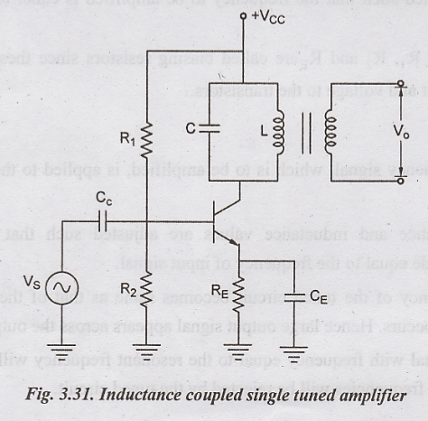
If
the output is taken across an inductor, then the tuned circuit is called
inductively coupled tuned circuit. It is otherwise called as transformer
coupled tuned circuit. Fig.3.31 shows the circuit diagram of an inductively
coupled single tuned circuit.
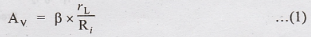
Gain and Frequency Response
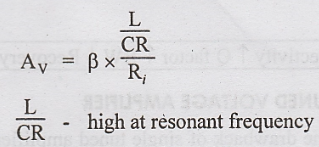
The
voltage gain depends upon current gain (β), input impedance Rf and
ac load resistance. The voltage gain is given by,
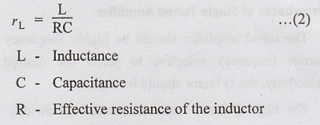
AC
load resistance of parallel resonant circuit is given by
Substitute
(2) in (1)
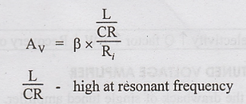
Thus
voltage gain of a tuned amplifier is very high at resonant frequency and
decreases as the frequency changes above or below the resonant frequency.
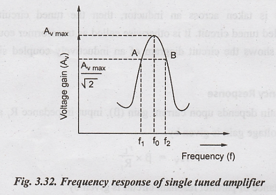
The
plot of voltage gain versus frequency is called frequency response.
The
bandwidth of a tuned amplifier is equal to difference in frequency between the
points A and B. At resonant frequency, the voltage gain drops to 1/√2 of its
maximum value.
Where
QO - Q-factor of tuned circuit
Drawbacks of Single Tuned Amplifier
The
tuned amplifier should be highly frequency selective to select the desired
carrier frequency selective to select the desired carrier frequency. For high
selectivity, the Q factor should be high.
The
high Q-factor leads to reduced bandwidth. This narrow bandwidth inturn result
in poor reproduction of audio signal. This is the main drawback of single tuned
amplifier.
Selectivity
↑ Q factor ↑ BW↓ Recovery of signal-poor
Electronic Devices and Circuits: Unit III: Multistage Amplifiers and Differential Amplifier : Tag: : Single Tuned Amplifiers - Small Signal Tuned Amplifiers
Related Topics
Related Subjects

Electronic Devices and Circuits
EC3353 - EDC - 3rd Semester - ECE Dept - 2021 Regulation | 3rd Semester ECE Dept 2021 Regulation