Signals and Systems: Unit III: Linear Time Invariant Continuous Time Systems,,
Realization of Systems in Direct Form
Realization of Systems in Direct Form II, Realization of Systems in Cascade Form, Realization of Systems in Parallel Form
Direct form-II realization has the advantage that, it uses minimum number of integrators. Instead of using separate integrators for integrating the input and output variable separately, an intermediate variable is integrated. The following examples illustrate the procedures to obtain direct form-II realization of continuous-time system described by the transfer functions or differential equations.
Realization
of Systems in Direct Form-ll
Direct form-II
realization has the advantage that, it uses minimum number of integrators.
Instead of using separate integrators for integrating the input and output
variable separately, an intermediate variable is integrated. The following
examples illustrate the procedures to obtain direct form-II realization of
continuous-time system described by the transfer functions or differential
equations.
Problem 4:
Realize an LTI system
with the following transfer function in direct form - II

Solution:
Given:

Divide the given
transfer function into two parts as follows:

Cross multiplying the
above equations, we get
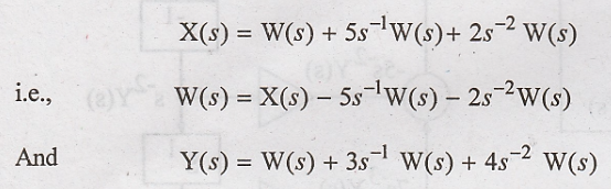
W(s) can be ralized as
shown in figure 3.8(a) and Y(s) can be realized as shown in figure 3.7(b)
cascading figures 3.8(a) and 3.8(b). We get the realization of H(s) as shown in
figure 3.9 since the inputs and outputs of the integrators are the same, they
can be treated as one as shown in figure 3.10.


Problem 5:
Realize the following
system in direct form - II. 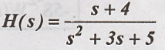
Solution:
Given:
Transfer function is
expressed in negative power of S as:

Dividing the transfer
function into two parts we have
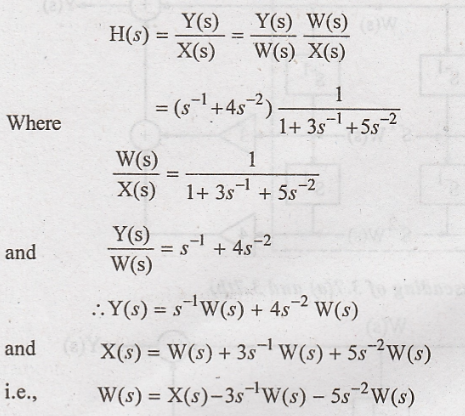
The given transfer
function is realized in direct form-II as shown in figure 3.11.

Problem 6:
Realize the system
described by the following differential equation in direct form-II:

Solution:
The given differential
equations is
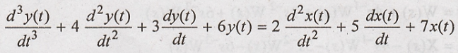
Taking Laplace
transform on both sides and neglecting initial conditions, we have

The transfer function
of the system is


Using the equation for Y(s) and W(s) the system transfer function is realized as shown in the figure 3.12.
Realization of Systems in Cascade Form
In cascade form
realization, the given transfer functions (of first and second order) and each
of these transfer functions are realized in direct form II, and then all those
realization structures are cascaded, I.e., connected in series, i.e., the
output of the first one is connected to the input of the second one, the output
of the second one to the input of the third and so on. The input is connected
to the first one and the output is taken form the last one.
Problem 7:
Realize the system with
transfer function H(s) =  in cascade form.
Solution:
The given transfer
function is:
Expressing it as a
product of several transfer function, we have

Each of these transfer
functions can be realized in direct form-II as shown in figure.


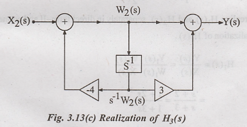
The individual
realization of H1(s), H2(s) and H3(s) are
connected in cascade to get the cascade realization of the transfer function
H(s) as shown in figure 3.14.

Problem 8:
Realize the system
described by the following transfer function H(s) =  in cascade
form.
in cascade
form.
Solution:
Given

In cascade form, H(s) =
Y(s) / X(s)
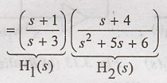
Now, realize H1(s)
and H2(s) separately in direct form-II and connect them in cascade.
Realization of H1(s).
Let

Where,

The realization of H1(s)
is shown in figure 3.15(a)

Realization of H2(s)

The realization of H2(s)
is shown in figure 3.15(b) is realized by cascading H1(s) and H2(s)
as shown in figure. 3.16.

Realization of Systems in Parallel Form
In parallel form
realization, the given transfer function is expressed into its partial
fractions and each factor is realized structures are connected in parallel,
i.e. The input is applied to each one of those structures and all the outputs
are added together.
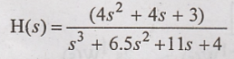
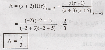
Problem 9:
Realize the system
given by the following transfer function in parallel form:
H(s)= 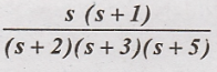
Solution:
The given transfer
function is;

In partial fraction
form, it is:

Where the coefficients
A, B, and C are:

To realize H(s),
realize H1(s), H2(s) and H3(s) separately as
shown in figure 3.17(a), 3.17(b), 3.17(c) and connect all of them in parallel
as shown in figure 3.18.


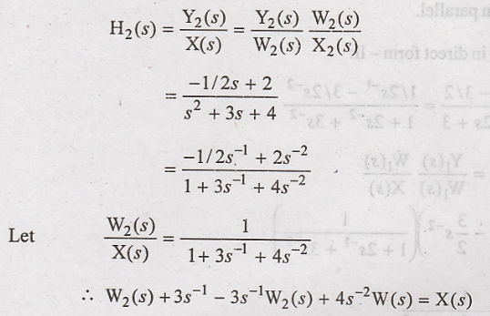
Problem 10:
Realize the system with
the following transfer function in parallel form:
H(s) = 
Solution:
The given transfer
function is:

In partial fraction
form, it is:

Now, to realize H(s) in
parallel form, realize H1(s) and H2(s) separatery in
direct form-II and connect them in parallel.
Realization of H1(s) in
direct form - II

Based on the equations
for W1(s) and Y1(s), H1(s) is realized as
shown in figure 3.19(a).

Realization of H2(s)
in direct form-II
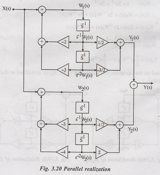

Based on these
equations for W2(s) and Y2(s), H2(s) is
realized as shown in figure 3.19(b). Now H(s) is realized by connecting H1(s)
and H2(s) in parallel as shown in figure 3.20.
Signals and Systems: Unit III: Linear Time Invariant Continuous Time Systems,, : Tag: : Realization of Systems in Direct Form II, Realization of Systems in Cascade Form, Realization of Systems in Parallel Form - Realization of Systems in Direct Form
Related Topics
Related Subjects

Signals and Systems
EC3354 - 3rd Semester - ECE Dept - 2021 Regulation | 3rd Semester ECE Dept 2021 Regulation