Electrical and Instrumentation Engineering: Unit V: Basics of Power Systems
Rating of the Neutral Grounding Resistor
Principle of Operation, Advantages, Disadvantages | Power Systems
Low Resistance Grounding is used for large electrical systems where there is a high investment in capital equipment or prolonged loss of service of equipment has a significant economic impact
Rating of The Neutral Grounding Resistor
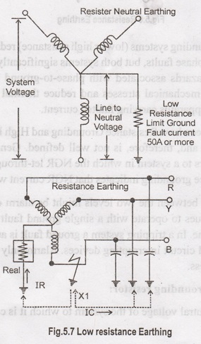
Voltage:
Line-to-neutral voltage of the system to which it is connected.
Initial Current:
The initial current which will flow through the resistor with rated voltage
applied.
Time:
The "on time" for which the resistor can operate without exceeding
the allowable temperature rise.
(i) Low Resistance Grounded
Low
Resistance Grounding is used for large electrical systems where there is a high
investment in capital equipment or prolonged loss of service of equipment has a
significant economic impact and it is not commonly used in low voltage systems
because the limited ground fault current is too low to reliably operate breaker
trip units or fuses. This makes system selectivity hard to achieve. Moreover,
low resistance grounded systems are not suitable for 4-wire loads and hence
have not been used in commercial market applications.
A
resistor is connected from the system neutral point to ground and generally
sized to permit only 200A to 1200 amps of ground fault current to flow. Enough
current must flow such that protective devices can detect the faulted circuit
and trip it off-line but not so much current as to create major damage at the
fault point.
Since
the grounding impedance is in the form of resistance, any transient over
voltages are quickly damped out and the whole transient overvoltage phenomena is
no longer applicable. Although theoretically possible to be applied in low
voltage systems (e.g. 480V),significant amount of the system voltage dropped
across the grounding resistor, there is not enough voltage across the arc
forcing current to flow, for the fault to be reliably detected.
For
this reason low resistance grounding is
not used for low voltage systems (under 1000 volts line to-line).
Advantages
i.
Limits phase-to-ground currents to 200-400A.
ii.
Reduces arcing current and, to some extent, limits arc-flash hazards associated
with phase-to-ground arcing current conditions only.
iii.
May limit the mechanical damage and thermal damage to shorted transformer and
rotating machinery windings.
Disadvantages:
i.
Does not prevent operation of over current devices.
ii.
Does not require a ground fault detection system.
iii.
May be utilized on medium or high voltage systems.
iv.
Conductor insulation and surge arrestors must be rated based on the line
to-line voltage. Phase-to-neutral loads must be served through an isolation
transformer.
v.
Used: Up to 400 amps for 10 sec are commonly found on medium voltage systems.
(ii) High Resistance Grounded
High
resistance grounding is almost identical to low resistance grounding except
that the ground fault current magnitude is typically limited to 10 amperes or
less. High resistance grounding accomplishes two things.
The
first is that the ground fault current magnitude is sufficiently low enough
such that no appreciable damage is done at the fault point. This means that the
faulted circuit need not be tripped off-line when the fault first occurs. Means
that once a fault does occur, we do not know where the fault is located. In
this respect, it performs just like an ungrounded system.
The
second point is it can control the transient overvoltage phenomenon present on
ungrounded systems if engineered properly.
Under
earth fault conditions, the resistance must dominate over the system charging
capacitance but not to the point of permitting excessive current to flow and thereby
excluding continuous operation.

High
Resistance Grounding (HRG) systems limit the fault current when one phase of
the system shorts or arcs to ground, but at lower levels than low resistance
systems. In the event that a ground fault condition exists, the HRG typically
limits the current to 5-10A.
HRG's
are continuous current rated, so the description of a particular unit does not
include a time rating. Unlike NGR's, ground fault current flowing through a HRG
is usually not of significant magnitude to result in the operation of an over
current device. Since the ground fault current is not interrupted, a ground
fault detection system must be installed.
These
systems include a bypass contactor tapped across a portion of the resistor that
pulses (periodically opens and closes). When the contactor is open, ground
fault current flows through the entire resistor. When the contactor is closed a
portion of the resistor is bypassed resulting in slightly lower resistance and
slightly higher ground fault current.
To avoid transient over-voltages,
an HRG resistor must be sized so that the amount of ground fault current
the unit will allow to flow exceeds the electrical system's charging current.
As a rule of thumb, charging current is estimated at 1A per 2000 KVA of system
capacity for low voltage systems and 2A per 2000 kVA of system capacity at
4.16kV.
These
estimated charging currents increase if surge suppressors are present. Each set
of suppressors installed on a low voltage system results in approximately 0.5A
of additional charging current and each set of suppressors installed on a
4.16kV system adds 1.5A of additional charging current.
A
system with 3000 kVA of capacity at 480 volts would have an estimated charging
current of 1.5A.Add one set of surge suppressors and the total charging current
increases by 0.5A to 2.0A. A standard 5A resistor could be used on this system.
Most resistor manufacturers nu detailed estimation tables that can be used to
more closely estimate an electrical system's charging current.
Advantages
i.
Enables high impedance fault detection in systems with weak capacitive visteixo
s balls a connection to earth some phase-to-earth faults are self-cleared.
ii.
The neutral point resistance can be chosen to limit the possible over voltage
transients to 2.5 times the fundamental frequency maximum voltage.
iii.
Limits phase-to-ground currents to 5-10A.
iv.
Reduces arcing current and essentially eliminates arc-flash hazards associated
with phase-to-ground arcing current conditions only.
v.
Will eliminate the mechanical damage and may limit thermal damage to shorted
transformer and rotating machinery windings.
vi.
Prevents operation of over current devices until the fault can be located (when
only one phase faults to ground).
vii.
May be utilized on low voltage systems or medium voltage systems up to 5kV.
IEEE Standard 141-1993 states that "high resistance grounding should be
restricted to 5kV class or lower systems with charging currents of about 5.5A
or less and should not be attempted on 15kV systems, unless proper grounding
relaying is employed".
viii.
Conductor insulation and surge arrestors must be rated based on the line
to-line voltage. Phase-to-neutral loads must be served through an isolation
transformer.
Disadvantages
i.
Generates extensive earth fault currents when combined with strong or moderate
olan capacitive connection to earth Cost involved.
ii. Requires a ground fault detection system to notify the facility engineer that a ground fault condition has occurred.
Electrical and Instrumentation Engineering: Unit V: Basics of Power Systems : Tag: : Principle of Operation, Advantages, Disadvantages | Power Systems - Rating of the Neutral Grounding Resistor
Related Topics
Related Subjects

Electrical and Instrumentation Engineering
BE3254 - 2nd Semester - ECE Dept - 2021 Regulation | 2nd Semester ECE Dept 2021 Regulation