Signals and Systems: Unit III: Linear Time Invariant Continuous Time Systems,,
Problems Based on Laplace Transform Analysis of CT System
Discuss about Problems Based on Laplace Transform Analysis of CT System.
Problems
Based on Laplace Transform Analysis of CT System.
Problem 1:
The tranafer function
of the system is given as H(s) =  Determine the impulse response if
the system is (i) stable (ii) causal. Whether this system will be stable and
causal simultaneously?
Determine the impulse response if
the system is (i) stable (ii) causal. Whether this system will be stable and
causal simultaneously?
Solution:
This system has 2
poles. They are s = -3 and s = 2. One pole lies on the right side and another
pole on the left side. Hence the system cannot be causal and stable
simultaneously. Impulse response for stable system.
For stable system ROC
of H(s) must include jo axis of s plane.

In the above figure,
pole at s = 2 lies on right side of Roc. Hence corresponding time domain signal
will be left sided.

Then pole s = -3 lies
on left half of Roc. Hence corresponding time domain signal will be right
sided.

Hence impulse response
becomes

(ii) Impulse response
of causal system.
For causal system all
the poles must lies on left side of Roc.
Here both the poles lie on left side of Roc. Hence time domain, signal will be right sided,

Roc: Re(s) > 2.
Hence impulse becomes h(t) =

Problem 2:
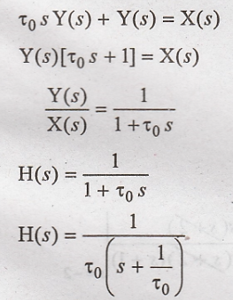
Determine the impulse
response h(t) of the system given by the differential equation  with all initial conditions to be zero.
Solution:
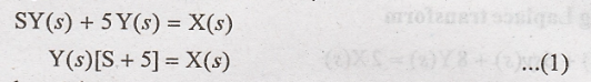
Taking Laplace
transform of given differential equation.

Take inverse laplace
transform of above equation,
Problem 3:
A stable system has the
input x(t) and output y(t). Use Laplace transform to determine the transfer
function and impulse response h(t) of the system given x(t) = e-2t
u(t); and y(t) = -2e-t u(t) + 2e-3t u(t).
Solution:
(i) Transfer function:

System transfer
function
H(s) = Y(s) / X(s)
By taking laplace
transform of x(t) we can get
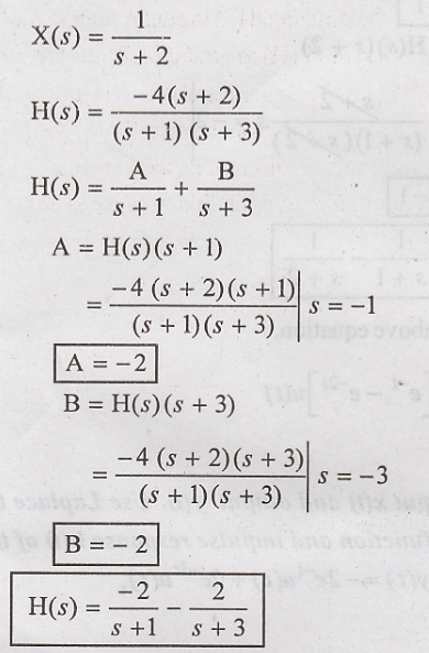
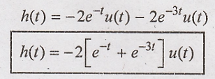
(ii) To obtain impulse
response of stable system.

ROC of Re(s) > -1
includes Re(s) > -3 and jω axis of s plane. Inverse laplace transform of
H(s) gives.
Problem 4:
The input and output of
a causal LTI system are related by the differential equation.  Find impulse response of the system. [May 11 - Marks 8]
Solution:
Talking Laplace
transform


Take inverse laplace
transform,

Problem 5:
Solve the differential
equation 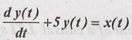 with initial condition y(o+) = -2 and input
x(t) = 3e-2t u(t).
with initial condition y(o+) = -2 and input
x(t) = 3e-2t u(t).
Solution:

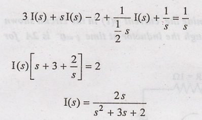
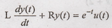
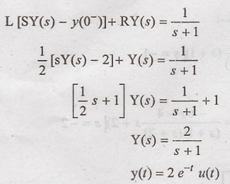
Taking Laplace trans
form on both sides,
But we know that
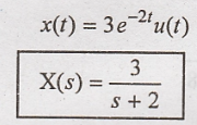
Now substitute X(s) in
(1)

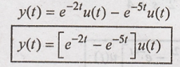
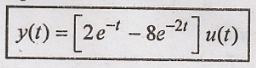
Taking inverse Laplace
transform
Problem 6:
Solve the following
differential equation 

Solution:
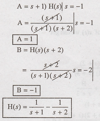
Taking Laplace
transform of given differential equation.

Take partial fraction
on above equation.

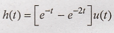
Taking inverse Laplace
transform of above equation.

Problem 7:
The circuit shown in
figure 3.34 represents a system with input x(t) and output y(t). Determine
response of the system y(t) using Laplace transforms, given R = 3Ω, L = 1H, C=
1/2. Farad, x(t) = u(t), the current through the inductor at t = 0-
is 2A. And the voltage across the capacitor at t = 0- is IV. [May
09-8 Marks]

Solution:

By Application KVL to
the laplace equivalent circuit.

Substitute (2) in (1)
But voltage across
inductor will be

Substitute the values
in above equation.

Taking inverse laplace
transform
Problem 8:
Use Laplace transform
to determine the current y(t) in the circuit shown in figure3.36. The current
through the inductor at time t = 0- is 2A for (i) x(t) = e-t
u(t) (ii) x(t)= cost u(t).

Solution:
Applying KVL to the
circuit
case
I:
Taking Laplace
transform
(ii) x(t) = cost u(t)
Applying KVL to the
circuit

Taking Laplace transform.

Taking inverse Laplace
transform of above equation
Problem 9:
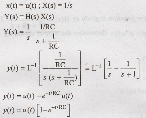
The input voltage to
the RC circuit is given as 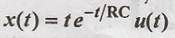 and the impulse response of this circuit
is given by
and the impulse response of this circuit
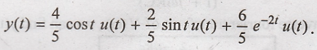
is given by 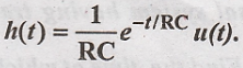 Find out out the out put y(t)
Solution:
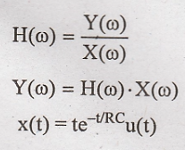
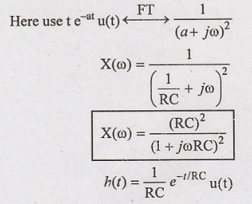

Taking inverse fourier
transform of Y(ω), we can find y(t)

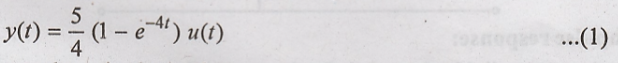
Problem 10:
A causal system having
transfer function H(s) = 1/s+4 is excited with x(t) = 5u(t). Find the time at
which output reaches 90% of its steady state value.
Solution:

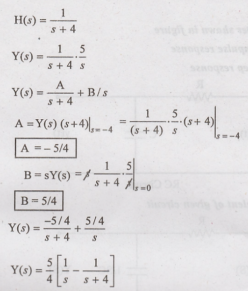
Taking Inverse Laplace
transform of above equation
Steady state volume is
obtained as

Hence 90% of above
steady state value is 
Substitute this value
for y(t) in (1)

Problem 11:
For the RC filter shown
in figure
(i) Obtain impulse
response
(ii) Obtain step
response

Laplace equivalent of
given circuit
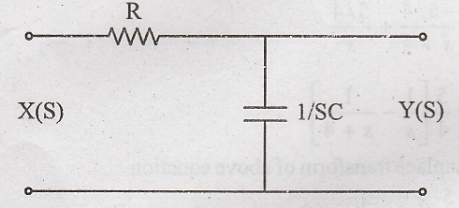
(i)
Impulse response:
Apply voltage divider
formula in Laplace equivalent circuit, we can write

(ii)
Step response:
Problem 12:
Find the impulse
response of the system given by 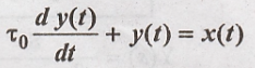 May 2002/8marks
Solution:
The given differential
equation is,

Taking Laplace
transform of above equation
Taking inverse Laplace
transform of a above equation

Problem 13:
The system transfer
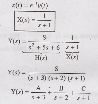
function is given as 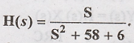 The input to the system is x(t) = e-t
u(t). Determine the output assuming zero initial conditions.
The input to the system is x(t) = e-t
u(t). Determine the output assuming zero initial conditions.
Solution:

The given input signal
x(t) is


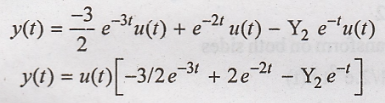
Taking inverse laplace
transform on both sides
Problem 14:
Find the steady state
response of the following systems to unit step excitations

Solution
:
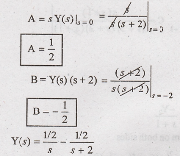
(i) H(s) = 1/S+1
Y(s) is calculated for
the unit step input

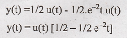
Taking inverse Laplace
transform on both sides
(ii) 
Solution
Y(s) is calculated for
the unit step input u(t)


Taking Laplace
transform on the sides

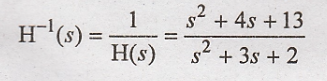
Problem 15:
The impulse response of
the system is given as  Determine the transfer function of the
inverse system.
Determine the transfer function of the
inverse system.
Solution:
The given impulse
response is

By taking Laplace
transform.

The transfer function
of the inverse system is given as
Problem 16:
Find the step response
of the system whose impales response is given as h(t) = u(t + 1)- u(t − 1)
[Dec-11/4 marks]
Solution:
Impulse response is
given as h(t) = u(t+1)-a(t-1)
Taking Laplace
transform of given impulse response.

Input is unit step
signal, hence X(s) = 1/s

Taking inverse Laplace
transform of above equation.

Signals and Systems: Unit III: Linear Time Invariant Continuous Time Systems,, : Tag: : - Problems Based on Laplace Transform Analysis of CT System
Related Topics
Related Subjects

Signals and Systems
EC3354 - 3rd Semester - ECE Dept - 2021 Regulation | 3rd Semester ECE Dept 2021 Regulation