Electronic Devices and Circuits: Unit I: Semiconductor Devices
PN Diode as Rectifier
Half wave Rectifier
A rectifier is an electrical device that converts alternating current (ac), which periodically reverses direction to direct current (dc), which flows in only one direction. This process is called as rectification.
PN DIODE AS RECTIFIER
A rectifier is an electrical device that converts alternating current (ac), which periodically reverses direction to direct current (dc), which flows in only one direction. This process is called as rectification. Rectifiers are used in power supplies for radio, television and computer equipment.
A
PN diode is a two terminal device which conducts and current flows though it
without any resistance during forward bias condition. When the diode is reverse
biased, the diode will not conduct due to high resistance and no current flows
through the diode i.e., diode is in OFF condition.
Thus
an ideal diode acts as a switch either ON or OFF depending on the voltage
applied to the diode, since ideal diode has zero resistance under forward bias
and infinite resistance under reverse bias.
HALF-WAVE RECTIFIER
In
half-wave rectifier, either positive or negative half of the ac signal is
passed, while the other half is blocked. It converts an ac voltage into a dc voltage
during one half of the ac cycle only.
PN
diode is used for rectification because of its unidirectional property ie
conducts during forward bias and does not conduct during forward bias and does
not conduct during reverse bias. Fig.1.22 shows the circuit diagram of half
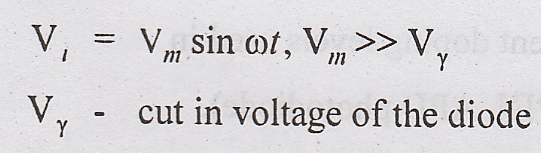
wave rectifier. Let Vi be the input voltage to the primary of the
transformer, and is given as
Where
During
positive half cycle of the input signal, the diode is forward biased and the
anode of the diode is more positive with respect to cathode. The diode
therefore conducts during positive cycle of the input voltage.
For
an ideal diode, the forward voltage drop is zero, thus the applied input
voltage will appear across the load resistance RL.
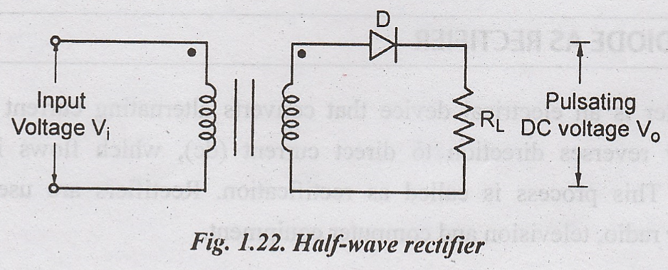

During
negative half cycle of the input signal, the diode is reverse biased i.e., the
anode of the diode is negative with respect to cathode. Thus the diode D does
not conduct due to high impedance. Hence the input voltage does not appear at
the output. Fig.1.23 shows the input and output waveform of half wave
rectifier.
Ripple Factor
The
ratio of rms value of ac component to the de component in the output is known
as Ripple Factor.
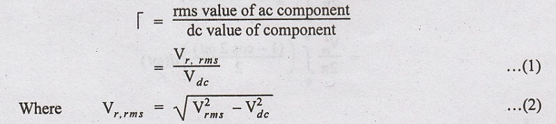
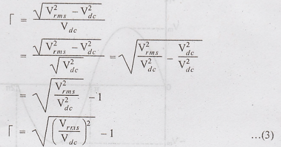
Substitute
(2) in (1)
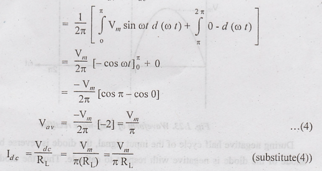
Average
voltage across load, Vav = Vdc
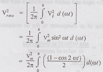
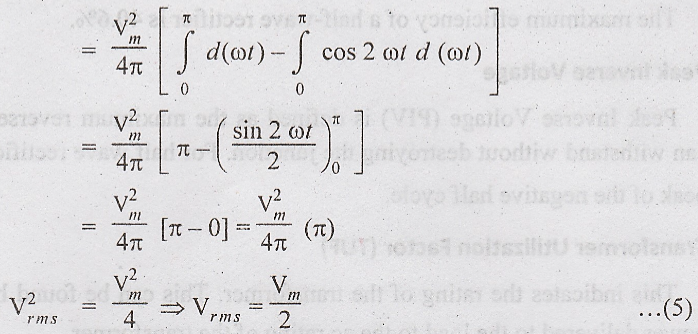
The
rms voltage at the load resistance is
Substitute
(3) & (4) in (5)
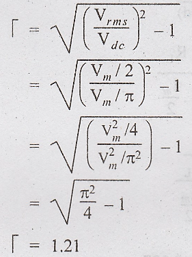
i.e.,
amount of ac present in the output is 121% of the de voltage.
Efficiency
The
efficiency η is defined as the ratio of dc output power to ac input power.
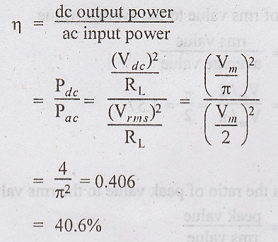
The
maximum efficiency of a half-wave rectifier is 40.6%.
Peak Inverse Voltage
Peak
Inverse Voltage (PIV) is defined as the maximum reverse voltage a diode can
withstand without destroying the junction. For half wave rectifier, PIV is Vm
i.e., peak of the negative half cycle.
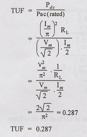
Transformer Utilization Factor
(TUF)
This
indicates the rating of the transformer. This can be found by the ratio of dc
power delivered to the load to the ac rating of the transformer.
Form factor
It
is defined as the ratio of rms value to the average value
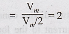
Peak Factor
Peak
Factor is defined as the ratio of peak value to the rms value.
Peak factor = peak value/rms value
Electronic Devices and Circuits: Unit I: Semiconductor Devices : Tag: : Half wave Rectifier - PN Diode as Rectifier
Related Topics
Related Subjects

Electronic Devices and Circuits
EC3353 - EDC - 3rd Semester - ECE Dept - 2021 Regulation | 3rd Semester ECE Dept 2021 Regulation