Electronic Devices and Circuits: Unit III: Multistage Amplifiers and Differential Amplifier
Neutralization
Methods, Hazeltine, Neutrodyne, Rice Neutralization, Neutralization Using Coil
In tuned amplifiers, the transistors are used at resonant frequency to amplify the narrow band of high frequencies. At this frequency, the junction capacitance between base and collector of the transistor becomes dominant. Thus the reactance of the circuit is low. This reactance provides a positive feedback which causes oscillations in the circuit and makes the system unstable.
NEUTRALIZATION
Need for Neutralization
In
tuned amplifiers, the transistors are used at resonant frequency to amplify the
narrow band of high frequencies.
At
this frequency, the junction capacitance between base and collector of the
transistor becomes dominant. Thus the reactance of the circuit is low.
This reactance provides a positive feedback which causes oscillations in the circuit and makes the system unstable.
To
prevent oscillation in tuned amplifiers, the neutralization technique is used.
NEUTRALIZATION METHODS
The
stage gain should be reduced to prevent oscillations in the circuit. This can
be done by
i.
Reducing Q
ii.
Stagger tuning
iii.
Loose coupling between the stages
The
feedback signal can be cancelled by an additional feedback signal that is equal
in amplitude and opposite in phase. i.e., a portion of output signal is
feedback to the input with same amplitude but opposite phase. This is achieved
using neutralization.
Neutralization
can be done in three methods.
i.
Hazeltine Neutralization
ii.
Neytrodyne Neutralization
iii.
Rice Neutralization
iv.
Neutralization using coil
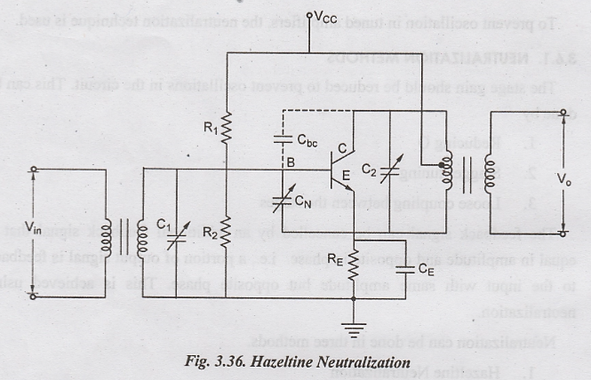
HAZELTINE NEUTRALIZATION
L.A.
Hazeltine introduced this circuit to increase the stability of the amplifiers.
Fig. 3.36 show the tuned amplifier with Hazeltine neutralization.
In
this circuit a small amount of variable capacitance CN is connected
from the bottom of the coil to the base of the transistor. The output coil in
center-tapped and the tap is used as the power supply feedpoint of the
amplifier.
This
capacitance feeds a signal with equal amplitude and opposite phase, which
cancels the interval capacitance Cbc from the top end of the coil.
Drawback
The capacitance value changes with time. The neutralizing capacitor should be adjusted correctly to completely neutralize the internal capacitance.
NEUTRODYNE NEUTRALIZATION
In
this circuit, the neutralization capacitor is connected from the lower end of
the base coil of next stage (secondary coil) to the base of the transistor.

Fig.
3.37 show the Neutrodyne neutralization circuit.
The
capacitor is connected with VCC and it is not sensitive to changes
in the supply voltage. It also provides high stability.
Advantages
i.
The capacitor is insensitive to variations in VCC.
ii.
High stability.
RICE NEUTRALIZATION
Fig.
3.38 show the Rice Neutralization circuit. It uses a center tapped coil in the
base circuit. The signal voltages at the end of the tuned base coil are equal
and out of phase.

NEUTRALIZATION USING COIL
Fig. 3.39 show the neutralization of tuned amplifier using coil. In this method, part of the tuned circuit at the base of next stage is used for minimum coupling to other windings.
It
is made perpendicular to the coupled windings. The voltage across the inductor
will cancel the feedback signal produced by the collector base capacitance Cbc

Electronic Devices and Circuits: Unit III: Multistage Amplifiers and Differential Amplifier : Tag: : Methods, Hazeltine, Neutrodyne, Rice Neutralization, Neutralization Using Coil - Neutralization
Related Topics
Related Subjects

Electronic Devices and Circuits
EC3353 - EDC - 3rd Semester - ECE Dept - 2021 Regulation | 3rd Semester ECE Dept 2021 Regulation