Electrical and Instrumentation Engineering: Unit IV: Measurements and Instrumentation
Moving Iron Type Instruments
Types, Construction, Working Principle, Torque Calculation | Indicating Instruments
This type of instrument is principally used for the measurement of alternating currents and voltages, though it can also be used for d.c. measurements.
MOVING IRON TYPE
This
type of instrument is principally used for the measurement of alternating
currents and voltages, though it can also be used for d.c. measurements. There
are two types of moving-iron instruments.
(i) Attraction type
in which a single soft-iron vane (or moving iron) is mounted on the spindle and
is attracted towards the coil when operating current flows through it.
(ii) Repulsion type
in which two soft-iron vanes are used; one fixed and attached to the stationary
coil while the other is movable (i.e. moving iron) and mounted on the spindle
of the instrument. When operating current flows through the coil, the two vanes
are magnetised, developing similar polarity at the same ends. Consequently,
repulsion takes place between the vanes and the movable vane causes the pointer
to move over the scale.
In
case the instrument is to be used as an ammeter, the coil has a fewer turns of
thick wire so that the ammeter has low resistance-a desirable requirement. In
case it is to be used as a voltmeter, the coil has a large number of turns of
fine wire so that the voltmeter has high resistance-a desirable requirement.
Attraction Type Moving Iron Type Instruments
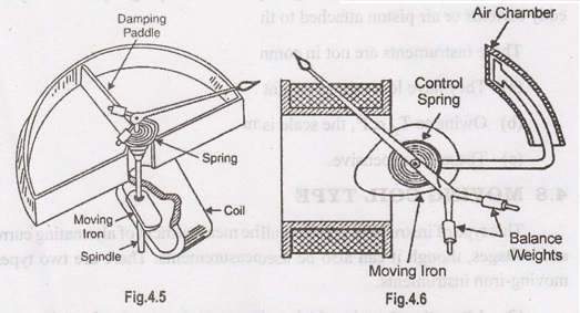
Fig.
4.5 shows the constructional details of an attraction type moving-iron
instrument. It consists of a cylindrical coil or solenoid which is kept fixed.
An oval-shaped soft-iron is attached to the spindle in such a way that it can
move in and out of the coil. A pointer is attached to the spindle so that it is
deflected with the motion of the soft-iron piece. The controlling torque is
provided by one spiral spring arranged at the top of the moving element. It
should be noted that in this instrument, the springs do not carry the current
as the same is carried by the stationary coil. The damping device is an
aluminum vane attached to the spindle, as shown in Fig4.5, which moves in a
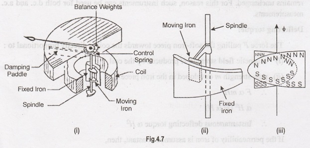
closed chamber. In some instruments, damping is provided by the movement of a
piston inside the curved chamber [See Fig. 4.6]; the piston being attached to
the spindle.
Working
When
the instrument is connected in the circuit to measure current or voltage, the
operating current flowing through the coil sets up a magnetic field. In other
words, the coil behaves like a magnet and therefore it attracts the soft-iron
piece towards it. The result is that the pointer attached to the moving system
moves from zero position. The pointer will come to rest at a position where
deflecting torque is equal to the controlling torque. If current in the coil is
reversed, the direction of magnetic field also reverses and so does the
magnetism produced in the soft-iron piece. Hence, the direction of the
deflecting torque remains unchanged. For this reason, such instruments can be
used for both d.c. and a.c. measurements.
Deflecting torque:
The
force F pulling the soft-iron piece towards the coil is directly proportional
to:
(i)
magnetic field strength H produced by
the coil
(ii)
pole strength m developed in the iron piece
F α mH
α H2 (m α H)
Instantaneous
deflecting torque a H2
If
the permeability of iron is assumed constant, then,
H α i,
where i is the instantaneous coil
current.
Instantaneous
deflecting torque a i2
Average
deflecting torque, Td α
mean of i2 over a cycle
Since
the instrument is spring controlled,
ΤC α θ
In
the steady position of deflection, Td
= Tc
θ α
mean of i2 over or a cycle
α I2 ...for d.c.
α I2 r.m.s. ...for a.c.
Since
the deflection is proportional to the *square of coil current, the scale of
such instruments is non-uniform; being crowded in the beginning and spread out
near the finish end of the scale.
Repulsion Type Moving Iron Type Instruments
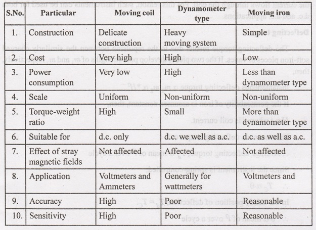
Fig.
4.7 (i) shows the constructional details of a repulsion type moving iron
instrument. It consists of two soft-iron pieces or vanes surrounded by a fixed
cylindrical hollow coil which carries the operating current. One of these vanes
is fixed and the other is free to move as shown in Fig. 4.7 (ii). The movable
vane is of cylindrical shape and is mounted axially on a spindle to which a
pointer is attached. The fixed vane, which is wedge-shaped and has a larger
radius, is attached to the stationary coil. The controlling torque is provided
by one spiral spring at the top of the instrument.
It
may be noted that in this instrument, springs do not provide the electrical
connections. Damping is provided by air friction due to the motion of a piston
in an air chamber.
Working
When
current to be measured or current proportional to the voltage to be measured
flows through the coil, a magnetic field is set up by the coil. This magnetic
field magnetizes the two vanes in the same direction i.e., similar polarities
are developed at the same ends of the vanes as shown in Fig. 4.7 (iii). Since
the adjacent edges of the vanes are of the same polarity, the two vanes repel
each other. As the fixed vane cannot move, the movable vane deflects and causes
the pointer to move from zero position.
The
pointer will come to rest at a position where deflecting torque is equal to the
controlling torque provided by the spring. If the current in the coil is
reversed, the direction of deflecting torque remains unchanged. It is because
reversal of the field of the coil reverses the magnetization of both iron vanes
so that they repel each other regardless of which way the current flows through
the coil. For this reason, such instruments can be used for both d.c. and a.c.
applications.
Deflecting torque:
The
deflecting torque results due to the repulsion between the similarly charged
soft-iron pieces or vanes. If the two pieces develop pole strengths of m1
and m2 respectively, then,
Instantaneous
deflecting torque a m1 m2 α * H2
If
the permeability of iron is assumed constant, then,
H α i
where i is coil current.
Instantaneous
deflecting torque α i2
Average
deflecting torque, Td α mean
of i2 over a cycle
Since
the instrument is spring-controlled,
ΤC α θ
In
the steady position of deflection, Td
= Tc
θ α mean of i2 over a cycle
α I2...for d.c.
α I2 r.m.s. ... for a.c.
Thus,
the deflection is proportional to the square of coil current as is the case
with attraction type moving-iron instruments. Therefore, the scale of such
instruments is also non-uniform; being crowded in the beginning and spread out
near the finish end of the scale. However, the non-linearity of the scale can
be corrected to some extent by the accurate shaping (e.g., using tongue-shaped
vanes) and positioning of iron vanes in relation to the operating coil.
Comparison of Moving Coil, Dynamometer type and Moving Iron Voltmeters and Ammeters
Table
below shows the comparison between permanent magnet moving coil (PMMC),
dynamometer type and moving iron voltmeters and ammeters.
Electrical and Instrumentation Engineering: Unit IV: Measurements and Instrumentation : Tag: : Types, Construction, Working Principle, Torque Calculation | Indicating Instruments - Moving Iron Type Instruments
Related Topics
Related Subjects

Electrical and Instrumentation Engineering
BE3254 - 2nd Semester - ECE Dept - 2021 Regulation | 2nd Semester ECE Dept 2021 Regulation