Electrical and Instrumentation Engineering: Unit IV: Measurements and Instrumentation
Moving Coil Type
Construction, Working Principle, Torque Calculation, Advantages, Disadvantages, Applications | Indicating Instruments
The basic principle of operation is that when a current carrying conductor is brought in a magnetic field (they should not be parallel to each other) a torque on the conductor is produced.
MOVING COIL TYPE
There
are two types of moving coil
1.
Permanent Magnet Moving Coil Type
2.
Dynamometer Type Moving Coil Instruments
1. Permanent Magnet Moving Coil Type
The
basic principle of operation is that when a current carrying conductor is
brought in a magnetic field (they should not be parallel to each other) a
torque on the conductor is produced. The instrument consists of a rectangular
coil pivoted so that its sides lie in the air gap between the two poles of a
permanent magnet and a soft-iron cylinder. The air gap between the magnet poles
and iron core is small and the flux density is uniform and is in a radial
direction, so that the flux lines are always at right angle to the current
carrying conductor and hence when current passes through the coil, a deflecting
torque is produced owing to the interaction between the two fluxes, one due to
permanent magnet and the other due to the magnetic field of the coil. This is
shown in Fig.4.2.
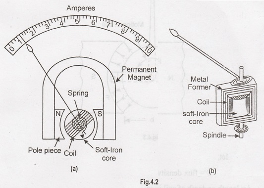
Construction:
Fig.
4.2 shows the various parts of a permanent-magnet moving coil instrument. It
consists of a light rectangular coil of many turns of fine wire wound on an
aluminum former inside which is an iron core as shown in Fig. 4.2 (a). The coil
is delicately pivoted upon jewel bearings and is mounted between the poles of a
permanent horse-shoe magnet. Attached to these poles are two soft-iron pole
pieces which concentrate the magnetic field. The current is led into and out of
the coil by means of two control hair-springs, one above and the other below
the coil, as shown in Fig. 4.2(b). These springs also provide the controlling
torque. The damping torque is provided by eddy currents induced in the aluminum
former as the coil moves from one position to another.
Working:
When
the instrument is connected in the circuit to measure current or voltage, the
operating current flows through the coil. Since the coil is carrying current
and is placed in the magnetic field of the permanent magnet, a mechanical
torque acts on it. As a result, the pointer attached to the moving system moves
in a clockwise direction over the graduated scale to indicate the value of
current or voltage being measured. If the current in the coil is reversed, the
deflecting torque will also be reversed since the direction of the field of the
permanent magnet is the same. Consequently, the pointer will try to deflect
below zero. Deflection in this direction (i.e. reverse direction) is prevented
by a spring "stop". Since the deflecting torque reverses with the
reversal of current in the coil, such instruments can be used to measure direct
currents and voltages only.
Deflecting torque:
The
magnetic field in the air gap is radial due to the presence of soft-iron core.
This means that conductors of the coil will always move at right angles to the
field. When current is passed through the coil, forces act on its both sides
which produce the deflecting torque. Referring to Fig.4.3
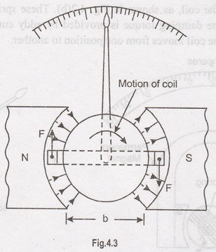
let,
B
= flux density in Wb/m2
l =
length or depth of coil in m
b
= breadth of coil in m
N
= No. of turns in the coil
If
a current of I amperes flows in the
coil, then force acting on each coil side is given by;
Force
on each coil side, F = B I l N
newtons
Deflecting
torque, Td = Force perpendicular
distance = (BIlN) × b
Td = B I N A
newton-metre
where
A (= b × l) is the area of the coil
in m2. Since the values of B,
N and A are fixed,
Td α I
The
instrument is spring-controlled so that TC
α θ.
The
pointer will come to rest at a position where
Td = TC
θ α I
Thus,
the deflection is directly proportional to the operating current. Hence, such
instruments have uniform scale [See. Fig. 4.2 (i)].
Advantages
(i)
Uniform scale i.e., evenly divided scale.
(ii)
Very effective eddy current damping because the aluminium former moves in an
intense magnetic field of the permanent magnet.
(iii)
High efficiency as it requires very little power for its operation.
(iv)
No hysteresis loss as the magnetic flux is practically constant.
(v)
External stray fields have little effect on the readings as the operating
magnetic field is very strong.
(vi)
Very accurate and reliable.
Disadvantages
(i)
Such instruments cannot be used for a.c. measurements.
(ii)
About 50% more expensive than moving-iron instruments because of their accurate
design.
(iii)
Some errors are caused due to variations (with time or temperature) either in
the strength of permanent magnet or in the control springs.
Applications:
Permanent-magnet
moving coil instruments are acknowledged to be the best type for all d.c.
measurements. They are very sensitive and maintain a high degree of accuracy
over long periods. The chief applications of such instruments are:
(i)
In the measurement of direct currents and voltages.
(ii)
In d.c. galvanometers to detect small currents.
(iii)
In ballistic galvanometers used mainly for measuring changes of magnetic flux linkages.
2. Dynamometer Type Moving Coil Instruments
In
this instrument the permanent magnet is replaced by one or two fixed coils
which carry current to be measured or a current proportional to the voltage to
be measured and which are connected either in series or parallel with the
moving coil. The coils are usually air cored. The torque of the instrument is
dependent upon the magnetic field strengths of the fixed and moving coil i.e.
the torque is proportional to square of the current in an ammeter and square of
the voltage in a voltmeter. Dynamometer instruments can thus be used in
alternating current circuits for which square law is essential. These can be as
well used for de circuits also.
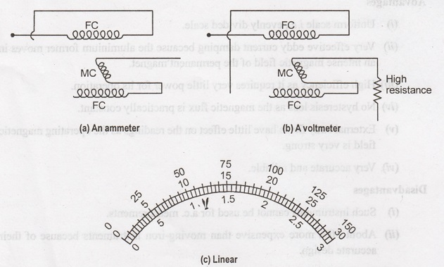
When
the meter is used as an ammeter Fig. 4. 4 (a) or as a voltmeter Fig. 4.4 (b),
the torque of the meter is proportional to the product if the flux of the fixed
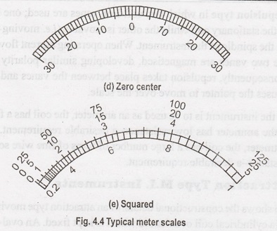
coil (FC) and the flux of the moving coil. The scale of the instrument is thus
a square one as shown in Fig. 4.4 (e).
Since
energy must be used to create two magnetic fields, the electrodynamometer
movement is less sensitive as compared to that in PMMC instruments.
The
control torque is provided by spring torque. The damping is provided by either
eddy currents or air piston attached to the pointer.
These
instruments are not in common use as
(a)
They have low torque/weight ratio
(b)
Owing to TD α I2
the scale is non uniform
(c)
These are expensive.
Electrical and Instrumentation Engineering: Unit IV: Measurements and Instrumentation : Tag: : Construction, Working Principle, Torque Calculation, Advantages, Disadvantages, Applications | Indicating Instruments - Moving Coil Type
Related Topics
Related Subjects

Electrical and Instrumentation Engineering
BE3254 - 2nd Semester - ECE Dept - 2021 Regulation | 2nd Semester ECE Dept 2021 Regulation