Electrical and Instrumentation Engineering: Unit V: Basics of Power Systems
Miniature Circuit Breakers
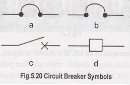
Symbols, Construction, Working Principle, Types
All fuses need to be replaced with MCB "Miniature Circuit Breaker" for better safety and control when they have done their job in the past. Unlike a fuse, an MCB operates as an automatic switch that opens in the event of excessive current flowing through the circuit and once the circuit returns to normal, it can be reclosed without any manual replacement.
MINIATURE CIRCUIT BREAKERS (MCBS)
All
fuses need to be replaced with MCB "Miniature Circuit Breaker" for
better safety and control when they have done their job in the past. Unlike a
fuse, an MCB operates as an automatic switch that opens in the event of
excessive current flowing through the circuit and once the circuit returns to
normal, it can be reclosed without any manual replacement.
"MCBs
are used primarily as an alternative to the fuse switch in most of the
circuits. A wide variety of MCBS have been in use nowadays with breaking
capacity of 10KA to 16 kA, in all areas of domestic, commercial and industrial
applications as a reliable means of protection."
An
MCB or miniature circuit breaker is an electromagnetic device that embodies a
complete enclosure in a molded insulating material. The main function of an MCB
is to switch the circuit, i.e., to open the circuit (which has been connected
to it) automatically when the current passing through it (MCB) exceeds the
value for which it is set. It can be manually switched ON and OFF as similar to
normal switch if necessary.
MCBs
are time delay tripping devices, to which the magnitude of overcurrent controls
the operating time. This means, these get operated whenever overloads exist
long enough to create a danger to the circuit being protected.
Therefore,
MCBs don't respond to transient loads such as switches surges and motor
starting currents. Generally, these are designed to operate at less than 2.5
milliseconds during short circuit faults and 2 seconds to 2 minutes in case of
overloads (depending on the level of current).
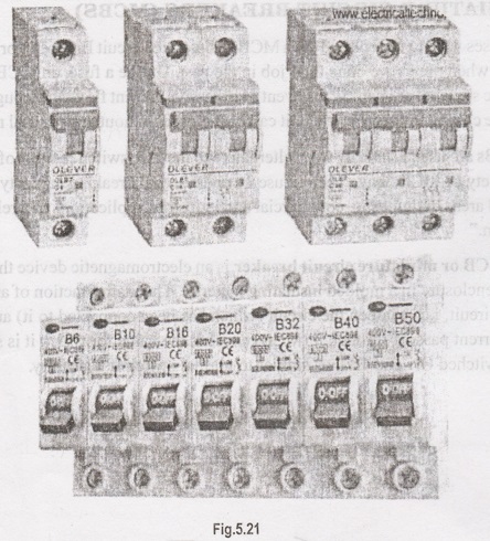
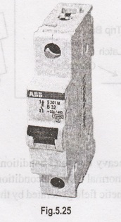
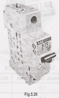
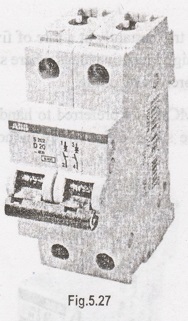
A
typical external appearance of an MCB is shown in figure. MCBs are manufactured
in different pole versions such as single, double, triple and four pole
structures with different fault current levels. Mostly, MCBs are linked to give
two and three-pole versions such that a fault in one line will break the
complete circuit and hence complete circuit isolation is provided. This feature
will be helpful in case of single phasing in three phase motor protection.
These
are rated at 220V for DC supply and 240/415 for AC supply (single and three-
phase) with different short circuit current capacity. Typically, single phase
devices have load current range of up to 100 A. Some MCBS have facility to
adjust its tripping current capacity while some devices are fixed for some load
current and short circuit rating.
MCBs
are used to perform many functions such as local control switches, isolating
switches against faults and overload protection devices for installations or specific
equipment or appliances.
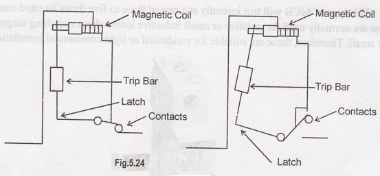
Construction of MCB
An
MCB embodies a complete enclosure in a molded insulating material. This
provides mechanically strong and insulated housing. The switching system
consists of a fixed and a moving contact to which incoming and outgoing wires
are connected. The metal or current carrying parts are made up of electrolytic
copper or silver alloy depending on the rating of the circuit breaker.
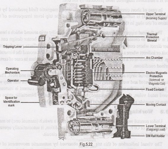
As
the contacts are separated in the event of an overload or short circuit
situation, an electric arc is formed. All modern MCBs are designed to handle
arc interruption processes where arc energy extraction and its cooling are
provided by metallic arc splitter plates. These plates are held in a proper
position by an insulating material. Also, arc runner is provided to force the
arc that is produced between the main contacts.
The
operating mechanism consists of both magnetic tripping and thermal tripping
arrangements.
The
magnetic tripping arrangement essentially consists of a composite magnetic
system that has a spring loaded dashpot with a magnetic slug in a silicon
fluid, and a normal magnetic trip. A current carrying coil in the trip
arrangement moves the slug against spring towards a fixed pole piece. So the
magnetic pull is developed on the trip lever when there is a sufficient
magnetic field produced by the coil.
In
case of short circuits or heavy overloads, strong magnetic field produced by
the coils (Solenoid) is sufficient to attract the armature of the trip lever
irrespective of the position of the slug in the dashpot.
The
thermal tripping arrangement consists of a bimetallic strip around which a
heater coil is wound to create heat depending on the flow of current. The
heater design can be either direct where current is passed through a bimetal
strip which affects part of electric circuit or indirect where a coil of
current carrying conductor is wound around the bimetallic strip. The deflection
of a bimetallic strip activates the tripping mechanism in case of certain
overload conditions.
The
bimetal strips are made up of two different metals, usually brass and steel.
These metals are riveted and welded along their length. These are so designed
such that they will not heat the strip to the tripping point for normal
currents, but if the current is increased beyond rated value, the strip is
warmed, bent and trips the latch. Bimetallic strips are chosen to provide
particular time delays under certain overloads.
Working & Operation of MCB
Under
normal working conditions, MCB operates as a switch (manual one) to make the
circuit ON or OFF. Under overload or short circuit condition, it automatically
operates or trips so that current interruption takes place in the load circuit.
The
visual indication of this trip can be observed by automatic movement of the
operating knob to OFF position. This automatic operation MCB can be obtained in
two ways as we have seen in MCB construction; those are magnetic tripping and
thermal tripping.
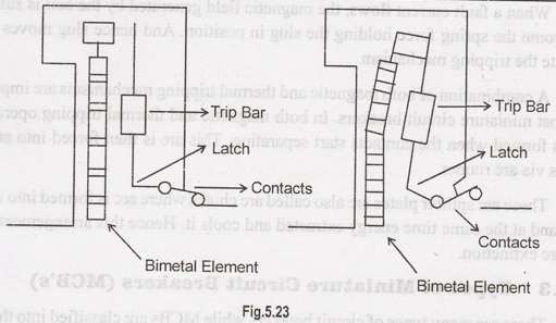
Under
overload conditions, the current through the bimetal causes it to raise the
temperature of it. The heat generated within the bimetal itself is enough to
cause deflection due to thermal expansion of metals. This deflection further
releases the trip latch and hence contacts get separated.
In
some MCBs, the magnetic field generated by the coil causes it to develop pull
on bimetals such that deflection activates the tripping mechanism.
Under
short circuit or heavy overload conditions, magnetic tripping arrangement comes
into the picture. Under normal working conditions, the slug is held in a
position by a light spring because the magnetic field generated by the coil is
not sufficient to attract the latch.
When
a fault current flows, the magnetic field generated by the coil is sufficient
to overcome the spring force holding the slug in position. And hence slug moves
and then actuate the tripping mechanism.
A
combination of both magnetic and thermal tripping mechanisms are implemented in
most miniature circuit breakers. In both magnetic and thermal tripping
operations, an arc is formed when the contacts start separating. This arc is
then forced into arc splitter plates via arc runner.
These
arc splitter plates are also called arc chutes where arc is formed into a
series of arcs and at the same time energy extracted and cools it. Hence this
arrangement achieves the arc extinction.
Types of Miniature Circuit Breakers (MCB's)
There
are many types of circuit breakers while MCBs are classified into three major
types according to their instantaneous tripping currents. They are
1.
Type B MCB
2.
Type C MCB
3.
Type D MCB
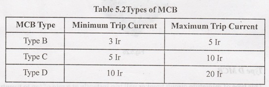
1. Type B MCB
This
type of MCB will trip instantly at a rate of three to five times its rated
current. These are normally used for resistive or small inductive loads where
switching surges are very small. Therefore, these are suitable for residential
or light commercial installations.
2. Type C MCB
This
type of MCB will trip instantly at a rate of five to ten times its rated
current. These are normally used for high inductive loads where switching
surges are high such as small electric motors and fluorescent lighting.
In
such cases, type C MCBS are preferred to handle higher values of short circuit
currents. Therefore, these are suitable for highly inductive commercial and
industrial installations.
3. Type D MCB
This
type of miniature circuit breaker will trip instantly at a rate of ten to
twenty five times its rated current. These are normally used for very high
inductive loads where high inrush current is very frequent.
These
are suitable for specific industrial and commercial applications. The common
examples of such applications include x-ray machines, UPS systems, industrial
welding equipment, large winding motors, etc.
The
above three types of MCBs provide protection within one tenth of a sec. The
minimum and maximum trip currents of these MCBS are given in a tabular form
below, where "Ir" is the rated current of the MCB.
MCBS
can also be classified based on the number of poles such as single pole, double
pole, triple pole and four pole MCBs.
Table
5.2Types of MCB
Electrical and Instrumentation Engineering: Unit V: Basics of Power Systems : Tag: : Symbols, Construction, Working Principle, Types - Miniature Circuit Breakers
Related Topics
Related Subjects

Electrical and Instrumentation Engineering
BE3254 - 2nd Semester - ECE Dept - 2021 Regulation | 2nd Semester ECE Dept 2021 Regulation