Electrical and Instrumentation Engineering: Unit V: Basics of Power Systems
Methods of Earthing
Power Systems
n this, cast Iron plate of size 600 mm × 600 mm × 6.3 mm thick plate is being used as earth plate. This is being connected with hot dip GI main earth strip of size 50mm breadth × 6mm thick x 2.5 meter long by means of nut, bolts and washers of required size.
METHODS OF EARTHING
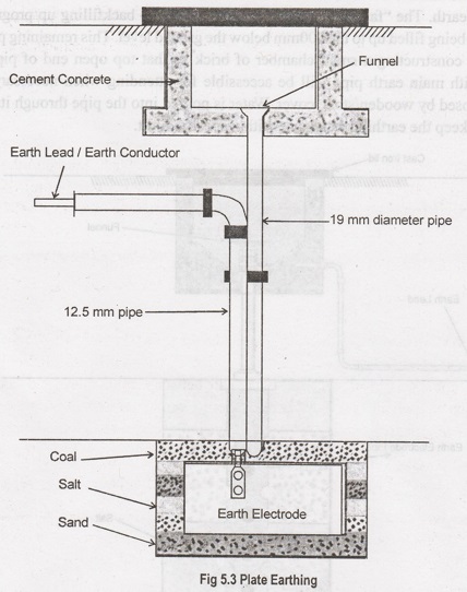
1. Plate Type Earthing
In
this, cast Iron plate of size 600 mm × 600 mm × 6.3 mm thick plate is being
used as earth plate. This is being connected with hot dip GI main earth strip
of size 50mm breadth × 6mm thick x 2.5 meter long by means of nut, bolts and
washers of required size. The main earth strip is connected with hot dip GI
strip of size 40mm × 3mm of required length as per the site location up to the
equipment earth / neutral connection. The earth plate is back filled and
covered with earthing material (mixture of charcoal & salt) by 150mm from
all six sides. The remaining pit is back filled with excavated earth. Along
with earth plate, rigid PVC pipe of 2.5 meter long is also provided in the
earth pit for watering purpose for to keep the earthing resistance within
specific limit.
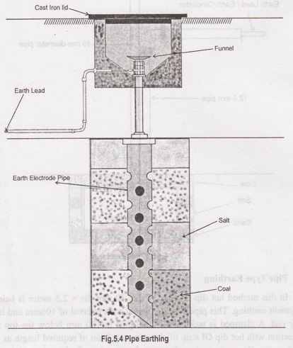
2. Pipe Type Earthing
In
this method hot dip GI pipe of size 40 mm dia x 2.5 meter is being used for
equipment earthing. This pipe is perforated at each interval of 100mm and is
tapered at lower end. A clamped is welded with this pipe at 100 mm below the
top for making connection with hot dip GI strip of size 40mm x 3mm of required
length as per the site location up to the equipment earth / neutral connection.
On its open end funnel is being fitted for watering purpose. The earth pipe is
placed inside 2700 mm depth pit. A 600mm dia "farma" of GI sheet or
cement pipe in two halves is are placed around the pipe. Then the angular space
between this "farma" and earth pipe is back filled with alternate layer
of 300mm height with salt and charcoal. The remaining space outside
"farma" will be backfilled by excavated earth. The "farma"
is gradually lifted up as the backfilling up progresses. Thus the pit is being
filled up to the 300mm below the ground level. This remaining portion is
covered by constructing a small chamber of brick so that top open end of pipe
and connection with main earth pipe will be accessible for attending when
necessary. The chamber is closed by wooden/stone cover. Water is poured into
the pipe through its end funnel to keep the earthing resistance within specific
limit.
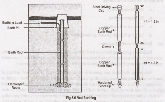
3. Rod Earthing
It
is the same method as pipe earthing. A copper rod of 12.5mm (1/2 inch) diameter
or 16mm (0.6in) diameter of galvanized steel or hollow section 25mm (1 inch) of
GI pipe of length above 2.5m (8.2 ft) are buried upright in the earth manually
or with the help of a pneumatic hammer. The length of embedded electrodes in
the soil reduces earth resistance to a desired value.
4. Earthing through the Waterman
In
this method of earthing, the waterman (Galvanized GI) pipes are used for
earthing purpose. Make sure to check the resistance of GI pipes and use
earthing clamps to minimize the resistance for proper earthing connection.
If
stranded conductor is used as earth wire, then clean the end of the strands of
the wire and make sure it is in the straight and parallel position which is
possible then to connect tightly to the waterman pipe.
5. Strip or Wire Earthing
In
this method of earthing, strip electrodes of cross-section not less than 25 mm
x 1.6 mm (1 in x 0.06 in) is buried in a horizontal trenches of a minimum depth
of 0.5 m. If copper with a cross-section of 25 mm x 4 mm (1 in x 0.15 in) is
used and a dimension of 3.0 mm2 if it's a galvanized iron or steel.
If
at all round conductors are used, their cross-section area should not be too
small, say less than 6.0mm2 if it's a galvanized iron or steel. The length of
the conductor buried in the ground would give a sufficient earth resistance and
this length should not be less than 15m.
Other Types of Earthing:
When the capabilities of certain equipment are limited, they may not with stand
certain fault currents then the following types of earthing are resorted to
limit the fault current.
a.
Resistance earthing
b.
Reactance earthing
c.
Peterson coil earthing.
d.
Earthing through grounding transformer.
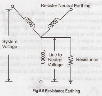
a. Resistance earthed systems
Resistance
grounding has been used in three-phase industrial applications for many years
and it resolves many of the problems associated with solidly grounded and
ungrounded systems. Resistance Grounding Systems limits the phase-to-ground
fault currents.
Grounding
Resistors are generally connected between ground and neutral of transformers,
generators and grounding transformers to limit maximum fault current as per
Ohms Law to a value which will not damage the equipment in the power system and
allow sufficient flow of fault current to detect and operate Earth protective
relays to clear the fault. Although it is possible to limit fault currents with
high resistance Neutral grounding Resistors, earth short circuit currents can
be extremely reduced. As a result of this fact, protection devices may not
sense the fault.
Therefore,
it is the most common application to limit single phase fault currents with low
resistance Neutral Grounding Resistors to approximately rated current of
transformer and/or generator.
In
addition, limiting fault currents to predetermined maximum values permits the
designer to selectively coordinate the operation of protective devices, which
minimizes system disruption and allows for quick location of the fault.
There
are two categories of resistance grounding:
(i)
Low resistance Grounding
(ii)
High resistance Grounding
Ground
fault current flowing through either type of resistor when a single phase
faults to ground will increase the phase-to-ground voltage of the remaining two
phases. As a result, conductor insulation and surge arrestor ratings must be
based on line-to-line voltage. This temporary increase in phase-to-ground
voltage should also be considered when selecting two and three pole breakers
installed on resistance grounded low voltage systems.
The
increase in phase-to-ground voltage associated with ground fault currents also
precludes the connection of line-to-neutral loads directly to the system. If
line-to neutral loads (such as 277V lighting) are present, they must be served
by a solidly grounded system. This can be achieved with an isolation
transformer that has a three-phase delta primary and a three-phase, four-wire,
wye secondary.
Neither
of these grounding systems (low or high resistance) reduces arc-flash hazards
associated with phase-to-phase faults, but both systems significantly reduce or
essentially eliminate the arc-flash hazards associated with phase-to-ground
faults. Both types of grounding systems limit mechanical stresses and reduce
thermal damage to electrical equipment, circuits, and apparatus carrying
faulted current.
The
difference between Low Resistance Grounding and High Resistance Grounding is a
matter of perception and, therefore, is not well defined. Generally speaking
high- resistance grounding refers to a system in which the NGR let-through
current is less than 50 to 100 A. Low resistance grounding indicates that NGR
current would be above 100 A.
A
better distinction between the two levels might be alarm only and tripping. An
alarm-only system continues to operate with a single ground fault on the system
for an unspecified amount of time. In a tripping system a ground fault is
automatically removed by protective relaying and circuit interrupting devices.
Alarm-only systems usually limit NGR current to 10 A or less.
b. Resonant earthed system
Adding inductive reactance from the system neutral point to ground is an easy method of limiting the available ground fault from something near the maximum 3 phase short circuit capacity (thousands of amperes) to a relatively low value (200 to 800 amperes).
To limit the reactive part of the earth fault current in a power system a neutral point reactor can be connected between the transformer neutral and the station earthing system.
A system in which at least one of the neutrals is connected to earth through an
i. Inductive reactance.
ii. Petersen coil / Arc Suppression Coil / Earth Fault Neutralizer.
The current generated by the reactance during an earth fault approximately compensates the capacitive component of the single phase earth fault current, is called a resonant earthed system.
The system is hardly ever exactly tuned, i.e. the reactive current does not exactly equal the capacitive earth fault current of the system.
A system in which the inductive current is slightly larger than the capacitive earth fault current is over compensated. A system in which the induced earth fault current is slightly smaller than the capacitive earth fault current is under compensated.
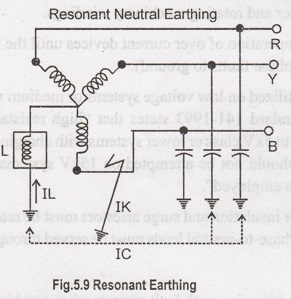
However, experience indicated that this inductive reactance to ground resonates with the system shunt capacitance to ground under arcing ground fault conditions and creates very high transient over voltages on the system. To control the transient over voltages, the design must permit at least 60% of the 3 phase short circuit current to flow underground fault conditions.
c. Petersen Coils
A Petersen Coil is connected between the neutral point of the system and earth, and is rated so that the capacitive current in the earth fault is compensated by an inductive current passed by the Petersen Coil. A small residual current will remain, but this is so small that any arc between the faulted phase and earth will not be maintained and the fault will extinguish. Minor earth faults such as a broken pin insulator, could be held on the system without the supply being interrupted. Transient faults would not result in supply interruptions.
Although the standard 'Peterson coil' does not compensate the entire earth fault current in a network due to the presence of resistive losses in the lines and coil, it is now possible to apply 'residual current compensation' by injecting an additional 180° out of phase current into the neutral via the Peterson coil. The fault current is thereby reduced to practically zero. Such systems are known as 'Resonant earthing with residual compensation', and can be considered as a special case of reactive earthing.
Resonant earthing can reduce EPR to a safe level. This is because the Petersen coil can often effectively act as a high impedance NER, which will substantially reduce any earth fault currents, and hence also any corresponding EPR hazards (e.g. touch voltages, step voltages and transferred voltages, including any EPR hazards impressed onto nearby telecommunication networks).
Advantages
i. Small reactive earth fault current independent of the phase to earth capacitance of the system.
ii. Enables high impedance fault detection.
Disadvantages
i. Risk of extensive active earth fault losses.
ii. High costs associated.
d. Earthing Transformers
For cases where there is no neutral point available for Neutral Earthing (e.g. for a delta winding), an earthing transformer may be used to provide a return path for single phase fault currents.
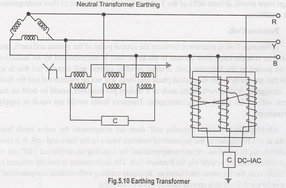
In such cases the impedance of the earthing transformer may be sufficient to act as effective earthing impedance. Additional impedance can be added in series if required. A special 'zig-zag' transformer is sometimes used for earthing delta windings to provide a low zero-sequence impedance and high positive and negative sequence impedance to fault currents.
Electrical and Instrumentation Engineering: Unit V: Basics of Power Systems : Tag: : Power Systems - Methods of Earthing
Related Topics
Related Subjects

Electrical and Instrumentation Engineering
BE3254 - 2nd Semester - ECE Dept - 2021 Regulation | 2nd Semester ECE Dept 2021 Regulation