Electrical and Instrumentation Engineering: Unit IV: Measurements and Instrumentation
Instrument Transformers
types with Construction, Working Principle
For measuring a large current in a d.c. circuit, we use low-range ammeter with a suitable shunt. The measurement of high d.c. voltage is made using a low-range voltmeter with a multiplier.
INSTRUMENT TRANSFORMERS
For
measuring a large current in a d.c. circuit, we use low-range ammeter with a
suitable shunt. The measurement of high d.c. voltage is made using a low-range
voltmeter with a multiplier.
However,
this method is not used for the measurement of high alternating currents and
voltages for many good reasons. In order to measure high alternating currents
and voltages, we employ specially designed transformers, called instrument transformers. These
transformers facilitate the a.c. measurements with low-range a.c. instruments.
There are two types of instrument transformers viz. (i) Current transformers
(ii) Potential transformers.
Current Transformer (C.T.)
A
current transformer (C.T.) is used to measure high alternating current in a
power system. The primary of this transformer has a few turns of thick wire
whereas the secondary has many turns of very fine wire as shown in Fig. 4.15.
It is clear from the figure that a current transformer is simply a well
designed step-up transformer. Since voltage is stepped up, the current is
stepped down which can be measured with a low-range a.c. ammeter.
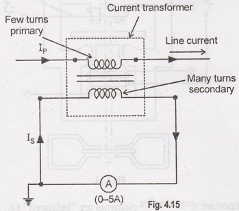
The
primary of the current transformer is connected in series with the line whose
current is to be measured as shown in Fig. 4.15. The secondary of the
transformer is connected across a low-range (0-5A) a.c. ammeter. The line
current (IP) and a.c. ammeter current (IS) are related
as:
NP
IP = NS IS
IP
/ IS = NS / NP
The
primary to secondary current ratio (i.e., IP / IS) is
called C.T. ratio (current transformation ratio)
I
= C.T. ratio
Or IP = IS × C.T. ratio
i.e., Line current (IP) = A.C. ammeter reading × C.T. ratio
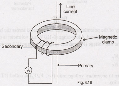
Fig.
4.16. It consists of a ring-shaped laminated core which carries the secondary
winding. The current carrying conductor itself acts as a one-turn primary that
simply passes through the centre of the ring. The position of the primary is
unimportant as long as it is more or less centred. This current transformer has
the arrangement to open and close the ring shaped core so that current can be
measured without opening the line.
The
clamp-on current transformers are simple and inexpensive and are widely used in
low-voltage (LV) and medium voltage (MV) lines in the power system.
Potential Transformer (P.T.)
A
potential transformer (P.T.) is used to measure high alternating potential
difference (voltage) in a power system. The primary of this transformer has
many turns while the secondary has few turns as shown in Fig. 4.17.
It
is clear from the figure that a potential transformer is simply a well-designed
step- down transformer. The stepped down voltage is measured with a low-range
a.c. voltmeter. The magnetic core of a potential transformer usually has a
shell-type construction for better accuracy. In order to provide adequate
protection to the operator, one end of the secondary winding is usually
grounded.
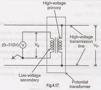
The
primary of the potential transformer is connected across the high-voltage line
whose voltage is to be measured. A low-range (0-110 V) a.c. voltmeter is
connected across the secondary. The line voltage (V) and a.c. voltmeter voltage
(V) are related as:
VP
/ VS = NP / NS
The
primary to secondary voltage ratio (i.e., VP / VS) is
called P.T. ratio (potential transformation ratio).
VP
/ VS = P.T. ratio
or
VP = VS P.T. ratio
i.e.
Line voltage (VP)=A.C. voltmeter reading × P.T. ratio
Advantages
of Instrument Transformers
In
order to measure high alternating currents and voltages in a power system, we
prefer instrument transformers to shunts and the following reasons:
(i)
The errors due to stray inductance and capacitance in shunts, multipliers and their
leads are eliminated.
(ii)
The measuring circuit is isolated from the mains by the transformer.
(iii)
We can use low-range and accurate a.c. instruments.
(iv)
The length of the connecting leads from the transformer to the instrument is of
lesser importance and leads may be of small cross-sectional area.
(v)
By using a clip-on type of transformer core, the current in a heavy-current
conductor can be measured without breaking the circuit.
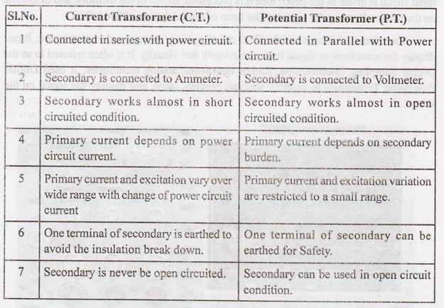
Difference between C.T. and PT.
Few
differences between C.T. and P.T. are listed below.
Electrical and Instrumentation Engineering: Unit IV: Measurements and Instrumentation : Tag: : types with Construction, Working Principle - Instrument Transformers
Related Topics
Related Subjects

Electrical and Instrumentation Engineering
BE3254 - 2nd Semester - ECE Dept - 2021 Regulation | 2nd Semester ECE Dept 2021 Regulation