Electronic Devices and Circuits: Unit I: Semiconductor Devices
Full Wave Rectifier
Full wave Bridge Rectifier
Full wave rectifier converts an ac voltage into pulsating dc voltage during both half cycles of the applied voltage.
FULL-WAVE RECTIFIER
Full
wave rectifier converts an ac voltage into pulsating dc voltage during both half
cycles of the applied voltage.
Here,
two diodes are used, one conducts during positive cycle and the other diode
conducts during negative half cycle of the applied voltage.
A
multiple winding transformer is used whose secondary winding is split equally
into two halves with a common centre tapped connection (C).
This
configuration results in each diode conducting in turn when its anode terminal
is positive with respect to the transformer center point C. This produces
output during both half cycles as shown in Fig.1.25.


The
full wave rectifier circuit consists of two diodes connected to a single load
resistance (R) with each diode supplying current to the load in turn. The
output voltage across the resistor R is the phasor sum of the two waveforms.
Ripple Factor

The
average voltage across the load resistance is

The
rms value of voltage at load resistance


Efficiency

The
maximum efficiency of a full wave rectifier is 81.2%
Transformer Utilization Factor
(TUF)
The
average TUF of full wave rectifier is 0.693.
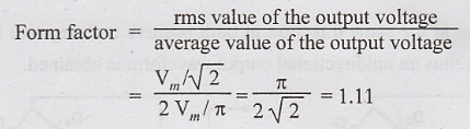
Form Factor
Peak Factor

Peak Inverse Voltage (PIV)
The peak inverse voltage for full-wave rectifier is 2 Vm.
FULL WAVE BRIDGE RECTIFIER
The
center tapping is eliminated in the bridge rectifier. In this rectifier, four
diodes are connected to form a bridge. The ac input voltage is applied to the
diagonally opposite ends of the bridge. The other two ends of the bridge are
connected to the load resistance. Fig.1.26 shows the bridge rectifier using
four diodes.

During
positive half cycle of the input voltage, diodes D1 and D3
conduct and diodes D2 and D4 do not conduct. The current
is produced due to diodes D1 and D3 and this current
flows through the load resistance RL.
During
negative half cycle of the input ac voltage, diodes D2 and D4
conduct and diodes D1, and D3 do not conduct. The current
flows in the load resistance due to diodes D2 and D4.
The
current flows in the same direction in both positive and negative half cycles
of the input voltage, thus an unidirectional output waveform is obtained.

The
maximum efficiency of a bridge rectifier is 81.2% and the ripple factor is
0.48. The PIV is Vm. Fig. 1.27 shows the output waveform of bridge
rectifier.

Table
1.3. Comparison of Rectifiers

Electronic Devices and Circuits: Unit I: Semiconductor Devices : Tag: : Full wave Bridge Rectifier - Full Wave Rectifier
Related Topics
Related Subjects

Electronic Devices and Circuits
EC3353 - EDC - 3rd Semester - ECE Dept - 2021 Regulation | 3rd Semester ECE Dept 2021 Regulation