Electrical and Instrumentation Engineering: Unit IV: Measurements and Instrumentation
Energy Meters
Single Phase Induction Type Energy Meter, Three-Phase Watthour Meter
The measurement of energy is the same process as measurement of power except that the instrument not merely indicates the power or rate of supply of energy but must take into account also the length of time for which the rate of energy is continued.
ENERGY METERS
The
measurement of energy is the same process as measurement of power except that
the instrument not merely indicates the power or rate of supply of energy but
must take into account also the length of time for which the rate of energy is
continued. There are basically three types of energy meters.
(a)
Electrolytic meters
(b)
Motor meters
(c)
Clock meters.
Out
of the above, motor meters are very widely used and among motor meters also
induction type watthour meters are more commonly used and will be dealt with
here.
Single Phase Induction Type Energy Meter
Single-phase
induction watthour meters (or energy meters) are extensively used for the
measurement of electrical energy in a.c. circuits. One can find such meters
installed in homes.
An
induction watthour meter is essentially an induction wattmeter with control
spring and pointer removed but brake magnet and counting mechanism provided.
Construction.
Fig.
4.12 shows the various parts of a single-phase induction watthour meter.
(i)
It consists of (a) two a.c.
electromagnets; the series magnet and shunt magnet (b) an aluminium disc or rotor placed between the two
electromagnets (c) brake magnet and (d) counting mechanism.
(ii)
The shunt magnet is wound with a fine wire of many turns and is connected
across the supply so that it carries current proportional to the supply
voltage.
Since
the coil of shunt magnet is highly *inductive, the current (and hence the -EB
ni le flux) in it lags the supply voltage by 90°.
The
series magnet is wound with a heavy wire of few turns and is connected in
series with the load so that it carries the load current. The coil of this
magnet is highly non-inductive so that angle of lag or lead is determined
wholly by the load.
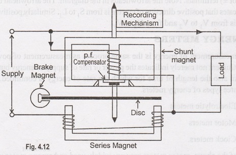
(iii)
A thin aluminium disc mounted on the spindle is placed between the shunt and
series magnets so that it cuts the fluxes of both the magnets.
(iv)
The braking torque is obtained by placing a permanent magnet near the rotating
disc so that the disc rotates in the field established by the permanent magnet.
Eddy currents induced in disc produce a braking or retarding torque that is
proportional to the disc speed.
(v)
A short-circuited copper loop (also known as power factor compensator) is provided on the central limb of the
shunt magnet. By adjusting the position of this loop, the shunt magnet flux can
be made to lag behind the supply voltage exactly by 90°.
Frictional
compensation is obtained by means of two adjustable short-circuited loops
placed in the leakage gaps of the shunt magnet. Geared to the rotating element
is counting mechanism which indicates the energy consumed directly in
kilowatthours (kWh).
Theory
When
induction watthour meter is connected in the circuit to measure energy, the
shunt magnet carries current proportional to the supply voltage and the series
magnet carries the load current. Therefore, expression for the driving torque
is the same as for induction wattmeter.
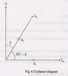
Referring
back to the phasor diagram in Fig. 4.13,
The
braking torque is due to the eddy currents induced in the aluminium disc. Since
the magnitude of eddy currents is proportional to the disc speed, the braking
torque will also be proportional to the disc speed n i.e.,
Braking
torque, TB α n
For
steady speed of rotation, Td = TB
..
Power α n
Multiplying
both sides by t, the time for which power is supplied
Power
× t α n t
or
Energy α N
where
N (= nt) is the total number of
revolutions in time t.
The
counting mechanism is so arranged that the meter indicates kilowatthours (kWh)
directly and not the revolutions.
Meter constant:
We
have seen above that:
N
α Energy
or
N = K × Energy
where
K is a constant called meter constant.
Meter
constant, K = N / Energy = No. of revolutions/kWh
Hence
the number of revolutions made by the disc for 1 kWh of energy consumption is
called meter constant.
The
meter constant is always written on the name plates of the energy meters
installed in homes, commercial and industrial establishments. If the meter
constant of an energy meter is 1500 rev./kWh, it means that for consumption of
1 kWh, the disc will make 1500 revolutions.
Three-Phase Watthour Meter
In
a 3-phase system, energy, like power, can be measured by means of two single-
phase watthour meters. The total energy supplied will be equal to the algebraic
sum of the two readings (a negative sign is used for the reading of the meter
which runs backward). However, this is never done commercially as it would be
more expensive and more troublesome than the use of a 3-phase meter.
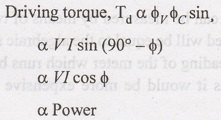
A
3-phase meter is merely a combination of two single-phase meters (See Fig.
4.14), with their moving elements mounted on the same spindle. The total
driving torque is equal to the sum of the torques exerted by both the moving
elements. Thus only one counting mechanism is required which will directly
indicate the energy being supplied to the 3- phase circuit. Fig. 4.14 shows how
a 3-phase watthour meter is connected in a 3-phase circuit to measure energy.
The current coils are connected in any two lines and each potential coil is
joined to the third line.
In
fact, the connections are similar to 2-wattmeter method used to measure power
in a 3-phase circuit.
It
is very important that the two elements are "balanced" i.e., the
driving torque of the two elements be exactly equal for equal amounts of power flowing
through each. If this is not done, the meter will not indicate correct reading
on unbalanced load. The balancing adjustment is most conveniently made with the
potential coils Connected in parallel and the current coils in series
opposition.
Electrical and Instrumentation Engineering: Unit IV: Measurements and Instrumentation : Tag: : Single Phase Induction Type Energy Meter, Three-Phase Watthour Meter - Energy Meters
Related Topics
Related Subjects

Electrical and Instrumentation Engineering
BE3254 - 2nd Semester - ECE Dept - 2021 Regulation | 2nd Semester ECE Dept 2021 Regulation