Electrical and Instrumentation Engineering: Unit V: Basics of Power Systems
Earthing
Working Principle, Needs, Safety measures | Power Systems
By earthing of electrical installations is meant the direct connection of all the metal non current carrying parts of electrical equipments e.g., metallic framework, body of electric machines, main switch, metallic covering of cables and conduits, distribution board, earth terminal of sockets etc. to earth plate.
EARTHING
By
earthing of electrical installations is meant the direct connection of all the
metal non current carrying parts of electrical equipments e.g., metallic
framework, body of electric machines, main switch, metallic covering of cables
and conduits, distribution board, earth terminal of sockets etc. to earth
plate. The earth plate is buried in the ground which has good electrical connection
to the surrounding earth. As far as domestic wiring is concerned the electric
utility provides earthing to its energy meter. But beyond the meter, earthing
is the responsibility of the owner of the house.
The
owner should make arrangements of his own earthing system with an independent
electrode. All appliances which are given connection through the socket outlet
e.g., refrigerator, washing machine, drier machine, table fan etc. should be
earthed through earth terminal of the socket outlet.
A
safe grounding system should provide the following:
(i)
A means to carry and dissipate electric currents into ground under normal and
abnormal operating conditions so that not only the equipment should remain safe,
the continuity of supply should also be maintained.
(ii)
The personnel working on or around the equipment should not experience any
electric shock.
We
will discuss here in detail the second aspect of grounding i.e., personnel
safety. For this it is important to understand the electrical characteristics
of the most important part of the circuit i.e., the human body.
It
is to be noted that human body experiences shock due to flow of current through
the body and not due to the voltage level. If the human body is properly
insulated he or she can even hold bare high voltage wire. It is a usual sight
to see birds sitting on the wire of h.t. lines.
However,
if the birds span the two HT wire simultaneously, it will turn into a dead
short circuit. In general, shock currents are classified based on severity of
the shock they cause e.g., currents which produce direct physiological harm are
termed primary shock currents, whereas, those that do not cause direct
physiological but may cause involuntary muscular reactions are called secondary
shock currents. It is to be noted that the threshold value of current which
gives a tingling sensation on the hand or finger when touching an electrically
live device differs from person to person. For a normal healthy person a
current of 1 mA is the threshold value to produce tingling sensation. Currents
of about 10 to 30 mA can cause lack of muscular control.
In
most of the cases a current of 100 mA will cause ventricular fibrillation.
Currents of higher magnitude may even completely stop the functioning of heart
or may cause severe electrical burns. Ventricular fibrillation is that
condition when the heart beats in an abnormal and ineffective manner with fatal
consequences. Therefore, the threshold value of current is the main criterion
for proper grounding of devices. Under threshold condition, there is rapid
uncoordinated contractions of the ventricles of the heart thereby the
synchronization between the heart beat and pulse beat is lost. When individual
muscle fibers contract independently, they are said to be fibrillating. Fibrillation
can occur in the atrial or ventricular muscles. During ventricular fibrillation
the ECG (Electrocardiogram) is totally disorganized.
A
human heart can be considered as a muscle operating rhythmically due to a nerve
pulse that provides the heart beat. Therefore, when an external signal due to
electric current is sent into the heart which will have different frequency,
different from that of the normal heart, it disturbs the rhythmic flow of
operation of heart. This condition of operation is known as ventricular
fibrillation or arrhythmic operation of heart. Once this arrhythmic condition
is set up, it is difficult to stop. It usually requires injection of another
electric current to stop the fibrillation and re-establish the normal rhythm.
5.1 give typical effects of Electric shocks current on humans.
Table
5.1. Typical effects of Electric shock currents on humans
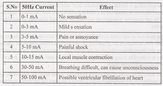
It
is to be noted that the effect of electric shock currents not only depends upon
the physiological features of a person but the psychologic factors also play an
important part. The effects of electric current on vital human organs not only
depend upon the magnitude of currents but it depends upon the duration and
frequency of the current. Humans are more vulnerable to electric shock current
at 50-60 Hz. The human body can withstand slightly higher current at 25 Hz and
almost five times larger for d.c. current. Similarly at frequencies of 1 KHz or
10 KHz even larger currents can be tolerated. In case of lightning (where the
frequency is very high and duration is in μ secs) the human body can withstand
μ very high currents in terms of several hundreds of amperes.
When
the human body becomes a part of the electric circuit the current that passes
through it, is limited by the body resistance and the resistance of the
earthing system of the device to which the person comes in contact. The human
body resistance differs from person to person and also it is different when two
feet or between one hand and one feet or between two hands. Generally two types
of potentials are important from electric shock point of view.
These
are
(i)
Touch potential and
(ii)
Step potential
When
a person touches the electrically live part of a device, the potential between
the hand and the foot is known as touch potential. However the potential
between the two feet of the person when walking on an electrically conducting
and live surface is known as step potential. Usually, the step potentials are
smaller in magnitude as compared to the touch potentials.
For
grounding a device, a galvanized steel wire is connected to it's body and the
other end of the wire is connected to a steel rod which is put into the ground
upto a certain depth. The pit contains moisturized mixture of salt and charcoal
to provide better conductivity.
The
steel rod or any other electrode is placed in this mixture. Sometimes more than
one rod are used to improve the grounding i.e., reduce the earthing resistance.
The earthing resistance also depends upon the resistivity of the soil. In
transmission lines, tower footing resistance is reduced by using radial or
parallel galvanized steel wires in the ground. These are known as counterpoise
wires.
The
acceptable value of grounding resistance varies upon its application e.g., for
domestic appliances, the acceptable value is about 1 ohm and for substation
equipment a 5 ohm resistance is acceptable. It is seen that the thickness of
the rod does not play a major role in reducing the ground resistance as does
the length of the rod. Therefore, it is better to use thin but long rods or
many small rods.
Some
of the safety measures to avoid electric shock are given below:
1.
See that all the metallic parts of various equipments and appliances are
properly earthed.
2.
Before energizing the domestic wiring its insulation must be checked.
3.
The phase wire must be connected through the switch.
4.
Never try to handle or operate any electrical appliances with wet hands or
standing on a wet floor.
5.
Make it a habit to switch off the supply and then pull out the plug whenever
you have finished with a particular gadget.
Need
of Earthing or Grounding
The
primary purpose of earthing is to avoid or minimize the danger of
electrocution, fire due to earth leakage of current through undesired path and
to ensure that the potential of a current carrying conductor does not rise with
respect to the earth than its designed insulation.
When
the metallic part of electrical appliances (parts that can conduct or allow
passage of electric current) comes in contact with a live wire, maybe due to
failure of installations or failure in cable insulation, the metal become
charged and static charge accumulates on it. If a person touches such a charged metal, the result is a severe
shock.
To
avoid such instances, the power supply systems and parts of appliances have to
be earthed so as to transfer the charge directly to the earth.
Below are the basic needs of Earthing
i.
To protect human lives as well as provide safety to electrical devices and
appliances from leakage current.
ii.
To keep voltage as constant in the healthy phase (If fault occurs on any one
phase).
iii.
To Protect Electric system and buildings form lighting.
iv.
To serve as a return conductor in electric traction system and communication.
v.
To avoid the risk of fire in electrical installation systems.
vi.
Safety of personnel
vii.
Safety of equipment. Prevent or at least minimize damage to equipment as a
boriu result viii. of flow of heavy currents.
ix.
Improvement of the reliability of the power system.
Different
Terms used in Electrical Earthing
Earth:
The proper connection between electrical installation systems via conductor to
the buried plate in the earth is known as Earth.
Earthed:
When an electrical device, appliance or wiring system connected to the earth
through earth electrode, it is known as earthed device or simple
"Earthed".
Solidly Earthed:
When an electric device, appliance or electrical installation is connected to
the earth electrode without a fuse, circuit breaker or resistance/ Impedance,
It is called "solidly earthed".
Earth Electrode:
When a conductor (or conductive plate) buried in the earth for electrical
earthing system It is known to be Earth Electrode. Earth electrodes are in
different shapes like, conductive plate, conductive rod, metal water pipe or
any other conductor with low resistance.
Earthing Lead:
The conductor wire or conductive strip connected between Earth electrode and
Electrical installation system and devices in called Earthing lead.
Earth Continuity Conductor:
The conductor wire, which is connected among of over 20 different electrical
devices and appliances like, distribution board, different plugs and appliances
etc. in other words, the wire between earthing lead and electrical device or
appliance is called earth continuity conductor. It may be in the shape of metal
pipe (fully or partial), or cable metallic sheath or flexible wire.
Sub Main Earthing Conductor:
A wire connected between switch board and distribution board i.e. that
conductor is related to sub main circuits.
Earth Resistance:
This is the total resistance between earth electrode and earth in 2 (Ohms).
Earth resistance is the algebraic sum of the resistances of earth continuity
conductor, earthing lead, earth electrode and earth.
Electrical and Instrumentation Engineering: Unit V: Basics of Power Systems : Tag: : Working Principle, Needs, Safety measures | Power Systems - Earthing
Related Topics
Related Subjects

Electrical and Instrumentation Engineering
BE3254 - 2nd Semester - ECE Dept - 2021 Regulation | 2nd Semester ECE Dept 2021 Regulation