Electronic Devices and Circuits: Unit V: Power Amplifiers and DC/DC Converters
Distortion in Amplifiers
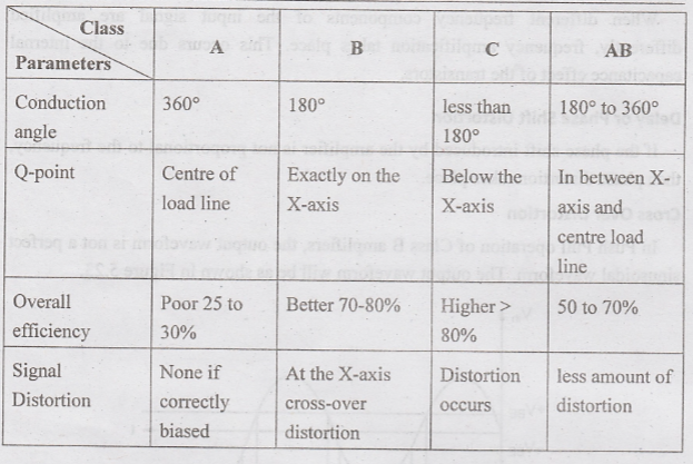
Comparison of Power Amplifiers
If the output of an amplifier is not a complete sine wave, then it is known as distortion using Fourier analysis, any distorted periodic waveform can be broken into different frequency components. These components are known as harmonics of the fundamental frequency. Harmonics are integer multiples of a fundamental frequency. For example. 1st harmonic is 1 x F KHz.
DISTORTION IN AMPLIFIERS
If
the output of an amplifier is not a complete sine wave, then it is known as
distortion using Fourier analysis, any distorted periodic waveform can be
broken into different frequency components. These components are known as
harmonics of the fundamental frequency. Harmonics are integer multiples of a
fundamental frequency. For example. 1st harmonic is 1 x F KHz.
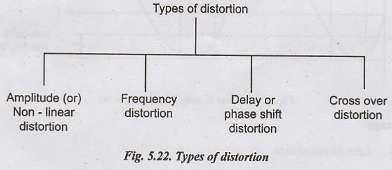
Amplitude (or) Non Linear Distortion
Due
to non-linear characteristics of the transistor, the output is different from
the input. This kind of distortion is known as amplitude or harmonic or
non-linear distortion. If fundamental frequency has amplitude A1 and
nth frequency, component has an amplitude of An.
Harmonic
distortion % D 
Second harmonic distortion occurs in class B and class AB amplifiers.
Frequency Distortion
When
different frequency components of the input signal are amplified differently,
frequency amplification takes place. This occurs due to the internal
capacitance effect of the transistors.
Delay or Phase Shift Distortion
If
the phase shift introduced by the amplifier is not proportional to the frequency,
then phase distortion takes place.
Cross Over Distortion
In
Push Pull operation of Class B amplifiers, the output waveform is not a perfect
sinusoidal waveform. The output waveform will be as shown in Figure 5.23.
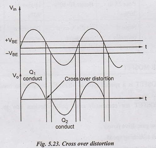
The
drive signal applied to class B transistor must reach a certain minimum level
before its collector current is properly in active region.
The Fig.5.23 initial rise of collector current in class B transistor lags the initial rise of input voltage. Also, the collector current prematurely drops to 0, when the input voltage approaches zero. Therefore, distortion occurs during each half-cycle due to combination of Class-B transistor. This distortion is known as cross over distortion, because it occurs when the composite waveform crosses the zero voltage axes.
COMPARISON OF POWER AMPLIFIERS
Electronic Devices and Circuits: Unit V: Power Amplifiers and DC/DC Converters : Tag: : Comparison of Power Amplifiers - Distortion in Amplifiers
Related Topics
Related Subjects

Electronic Devices and Circuits
EC3353 - EDC - 3rd Semester - ECE Dept - 2021 Regulation | 3rd Semester ECE Dept 2021 Regulation