Electronic Devices and Circuits: Unit III: Multistage Amplifiers and Differential Amplifier
Differential Amplifier
The differential amplifier is used to amplify the difference between two input signals. The differential amplifier may be implemented using BJTS or FETs and it is the commonly used building block in analog IC design.
DIFFERENTIAL AMPLIFIER
The
differential amplifier is used to amplify the difference between two input
signals.
The
differential amplifier may be implemented using BJTS or FETs and it is the
commonly used building block in analog IC design.
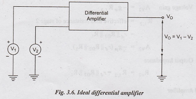
The
block diagram of an ideal differential amplifier is shown in Fig.3.6. It has
two input terminals and one output terminal. The two input signals V1
and V2 are given as input and connected to the input terminals. V1
and V2 are measured with respect to ground terminal.
The
output voltage VO is proportional to the difference between two
input signals V1 and V2.
i.e.,
V1 ∞ (V1 - V2)
Common Mode Signal
Common
mode refers to applying common input to both input terminals. A common signal
to both the input terminal is called as common mode signal.
The
output voltage for the common mode signal will be zero
VO
= V1 - V2
If
V1 = V2 = V
⇒ VO = 0
Practically
the output will not be zero, it produces some minimum amount of voltage.
Differentially Mode Signal
The
difference between the input signals is obtained as differential signal VO.
The
two input signals V1 and V2 are not same and it produces
the difference between these two signals as output.
VO
= V1 - V2
The
differential signal VO is amplified by the differential amplifier.
So it is called as differential amplifier.
Common Mode Gain (AC)
The
output of the differential amplifier can be modified as
VO = Ad (V1 - V2) ...(2)
Where
Ad - differential gain
Differential
gain can be defined as the gain with which the differential amplifier amplifies
the differential signal.
The
output signal also depends in the average input voltage, called common mode
signal VC, given by
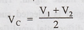
Common
mode gain is defined as the gain with which a practical differential amplifier
amplifies the common mode signal.
The
output voltage due to common mode signal is given by.
VO
= AC VC
Where
AC - common mode gain, VC - common mode signal
For
an ideal differential amplifier, the common mode gain should be Zero.
Differential Mode Gain (Ad)
As
mentioned earlier, the output is proportional to the differential gain, Ad
and the differential voltage Vd. The output voltage VO is
given by
VO
= Ad Vd ...(3)
Where
Ad
- differential gain
Vd
- differential voltage
The
differential gain can be written as
Differential
gain Ad - VO / Vd
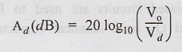
In
decibels, Ad can be expressed as
Common Mode Rejection Ratio (CMRR)
CMRR is defined as the ability of a differential amplifier to reject the common mode signal.
Need for Common Mode Rejection
The
common mode signal is the signal which is present at both the input terminals
of a differential amplifier. The best example of common mode signal is noise.
Practically, the output will not be zero for the common mode signal. The
differential signal produce a very small output voltage for common mode input
signal. It should be capable of rejecting the common mode signal. Thus CMRR is
required to determine how the common mode signal is rejected successfully. The
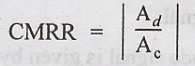
CMRR is otherwise called as figure of merit of a differential amplifier. CMRR
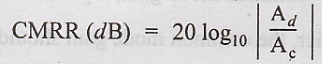
is defined as the ratio of differential gain Ad to the common mode
gain Ac.
For
an ideal differential amplifies CMRR should be infinity. In practical
situations, CMRR should be as high as possible. In dB, it is expressed as
Features
The
differential amplifier should have the following features
i.
High differential gain
ii.
Low common mode gain
iii.
High Common Mode Rejection Ratio (CMRR)
iv.
High input impedance
v.
Low output mpedance
vi.
High gain
vii.
Large bandwidth
Electronic Devices and Circuits: Unit III: Multistage Amplifiers and Differential Amplifier : Tag: : - Differential Amplifier
Related Topics
Related Subjects

Electronic Devices and Circuits
EC3353 - EDC - 3rd Semester - ECE Dept - 2021 Regulation | 3rd Semester ECE Dept 2021 Regulation