Electronic Devices and Circuits: Unit V: Power Amplifiers and DC/DC Converters
DC to DC Converters
Operation, Switching-Mode Regulator
The DC to DC converters convert one level of DC voltage to another level. It is also known as DC chopper. Different electronic devices require different operating voltages. Ex: ICs, MOSFET Also in industrial applications, a fixed voltage de source needs to be converted into a variable voltage de source. DC choppers are used to provide different voltage for each device. It can be used to step-up or step-down a dc voltage source.
DC TO DC CONVERTERS
The
DC to DC converters convert one level of DC voltage to another level. It is
also known as DC chopper.
Different
electronic devices require different operating voltages. Ex: ICs, MOSFET Also
in industrial applications, a fixed voltage de source needs to be converted
into a variable voltage de source. DC choppers are used to provide different
voltage for each device. It can be used to step-up or step-down a dc voltage
source.
APPLICATIONS
1. Traction motor control in electric automobiles, trolley cars/marine hoists, trucks, minehaulers. They provide smooth acceleration control, high efficiency fast response.
2.
Regenerative breaking of dc motors to return energy back into supply leading to
energy saving for transportation with frequent stops.
3.
In DC voltage regulators.
OPERATION OF DC-DC CONVERTER
The
DC-DC converter should be able to operate as a step up or step down voltage
supplier to provide constant load voltage over the entire battery voltage range
of operation. Fig.5.29 shows the basic diagram of DC to DC converter.
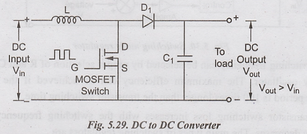
If
the switch is ON, then the inductor feeds the energy from the input and stores
in the form of magnetic energy. If the switch is OFF, it discharges the energy.
It is assumed that output of capacitor is sufficient for the time constant of
an RC circuit on the output side. The constant output voltage is considered as
the steady state.
Advantages
1.
Simplified power supply system.
2.
Provides isolation in the primary and secondary circuits from each other.
3.
Battery space can be reduced using converter.
4.
Used in regulation and control of DC voltage.
Disadvantages
1.
Switching converters lead to more noise.
2.
Expensive as it requires external circuit.
3.
Inadequate due to unsteady voltage and current supply.
4. More ripple current and high losses.
SWITCHING - MODE REGULATOR
The
dc choppers can be used as switching mode regulators for converting an
unregulated dc voltage to a regulated dc output voltage power BJT or power
MOSFET is used as a switching device and pulse-width modulator is done at a
fixed frequency. Fig.5.30 shows the diagram of switching regulators.
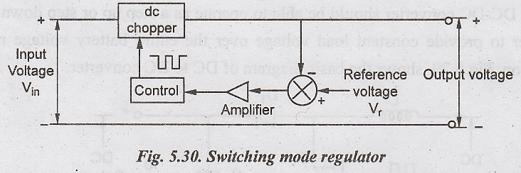
The
switching frequency can be selected by proper selection of R and C values of
frequency oscillator. The maximum efficiency can be achieved if the minimum
oscillator period is 100 times longer than the transistor switching time.
The
transistor switching loss increases with the switching frequency and the
efficiency decreases. The main types of switching regulators are
1.
Buck regulator
2.
Boost regulator
3.
Buck-Boost regulator
4.
Cuk regulator
Electronic Devices and Circuits: Unit V: Power Amplifiers and DC/DC Converters : Tag: : Operation, Switching-Mode Regulator - DC to DC Converters
Related Topics
Related Subjects

Electronic Devices and Circuits
EC3353 - EDC - 3rd Semester - ECE Dept - 2021 Regulation | 3rd Semester ECE Dept 2021 Regulation