Electronic Devices and Circuits: Unit V: Power Amplifiers and DC/DC Converters
Buck-Boost Converter
Construction, Operation, Advantages, Disadvantages
A Buck-Boost Regulator produces an output voltage which may be less than or greater than the input voltage. The polarity of output voltage is opposite to that of input voltage. So, this regulator is also known as inverting or flyback regulator.
BUCK - BOOST CONVERTER
A
Buck-Boost Regulator produces an output voltage which may be less than or
greater than the input voltage.
The
polarity of output voltage is opposite to that of input voltage. So, this
regulator is also known as inverting or flyback regulator.
Construction
Transistor
Q1 acts as switch. Diode is connected in series with the load. The
inductor L is connected in parallel after the switch and before the diode. A
capacitor C is connected in parallel with load. Fig. shows the circuit diagram
of Buck-Boost converter.

Operation
The circuit operation is divided into 2 modes.
Mode 1
Q1
is turned on and D1 is reverse biased. The input current increases
and flows through inductor L and transistor Q1.
Mode 2
Q1
is switched OFF.
i.
Current flowing through inductor L will flow through L, C, D1 and
load.
ii.
The energy stored in inductor L will be transferred to the load and the
inductor current will fall until Q1 is switched ON again in the next
cycle.
The
equivalent circuits for mode 1 and mode 2 are shown in Fig.5.40


For
continuous load current, the steady state voltages and currents waveform of the
buck-boost regulator is shown in Fig.5.41.
Assume
inductor current rises linearly from I1 to I2 in time t1.


The
inductor current falls linearly from I2 to I1 in time t2.

ΔI - Peak to peak ripple current of inductor L
Equate
ΔI in equation (3) and (5)

Substitute
t1 = KT and t2 = (1 - K) T
The
average output voltage is

Assume
lossless circuit,
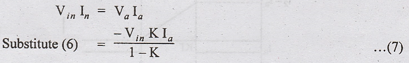
The
average input current is given by

where
Ia → average output current
Switching
period is given by

Substitute

When
transistor Q1 is ON, the capacitor supplies the load current for t =
t1.
The
average discharging current of the capacitor is IC = Ia.
Peak-to-peak
ripple voltage of capacitor is

Substitute

Advantages
1.
A buck-boost regulator doesnot use a transformer and provides output voltage
polarity reversal.
2.
High efficiency.
3.
Easy to implement short-circuit protection
4.
Less expensive.
Disadvantages
1.
Input current is discontinuous and high peak current flows through transistor Q1.
2. Slow response to fast load steps.
3.
As sensed voltage is negative, inverting op-amp is required for feedback and
closed loop control.
4.
No isolation between input and output.
Electronic Devices and Circuits: Unit V: Power Amplifiers and DC/DC Converters : Tag: : Construction, Operation, Advantages, Disadvantages - Buck-Boost Converter
Related Topics
Related Subjects

Electronic Devices and Circuits
EC3353 - EDC - 3rd Semester - ECE Dept - 2021 Regulation | 3rd Semester ECE Dept 2021 Regulation