Electronic Devices and Circuits: Unit V: Power Amplifiers and DC/DC Converters
Boost Regulator
Circuit Diagram, Equivalent Circuits, Derivations, Advantages, Disadvantages, Applications
The boost regulator produces an output voltage greater than input voltage. The circuit diagram of boost regulator using power MOSFET. The circuit operation has 2 modes.
BOOST REGULATOR
The
boost regulator produces an output voltage greater than input voltage. Fig.5.35
shows the circuit diagram of boost regulator using power MOSFET. The circuit
operation has 2 modes.
1. Mode 1
At
t = 0, Q1 is switched ON
The
input current flows through the inductor L and transistor Q1.
2. Mode 2
At
t = t1 Q1 is switched OFF
The
current flowing through transistor will not flow through L, C load and diode D1.
i.
The inductor current drops until transistor Q1 is turned ON again in
the next cycle.
ii.
The energy stored in inductor L is transferred to the load. Fig.5.35 shows the
equivalent circuit for mode 2.

Fig.5.36
shows the equivalent circuit for mode 1.
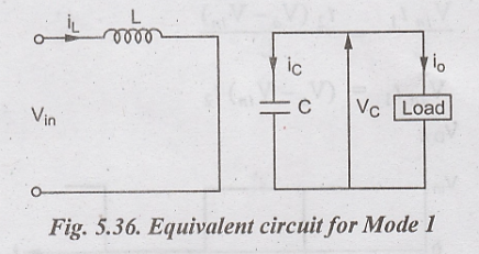
Fig.5.37
equivalent circuit for Mode 1
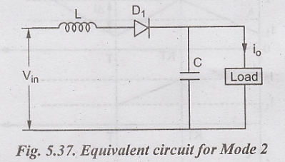
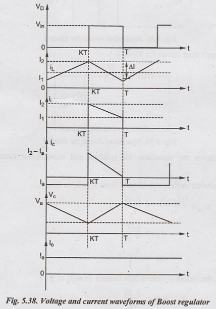
Fig.5.38
shows the waveform for voltages and currents for continuous load current.
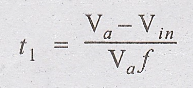
Assume
inductor current rise linearly from I1 to I2 in time t1,

In
time t2, the inductor current falls linearly from I2 to I1.
where ∆I - peak-to peak ripple current of inductor L
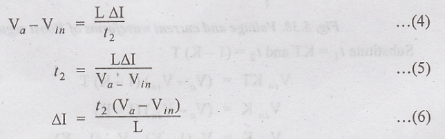
Equate
(3) and (4)

Substitute
t1 = KT and t2 = (1 - K) T

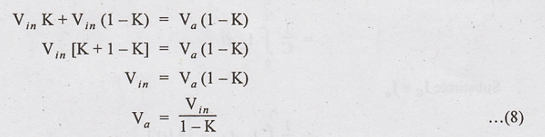
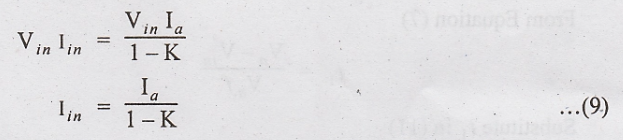
Assume
lossless transistor

Substitute
(7)
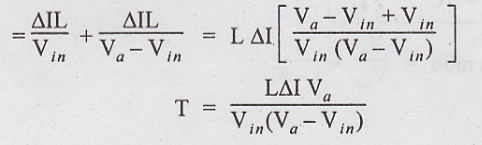
Switching
period T is given by
T
= t1 + t2
Substitute
(2) and (5)
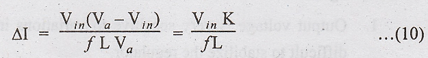
Peak-to-peak
ripple current,
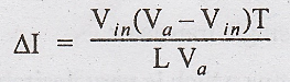
Substitute
T = 1/f
when
the transistor is ON, the capacitor supplies the load current for t = t1.
The
average capacitor current is IC = Ia
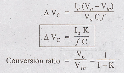
The
peak-to-peak ripple voltage of the capacitor is
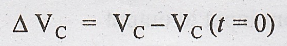
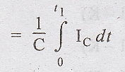
Substitute
IC = Ia
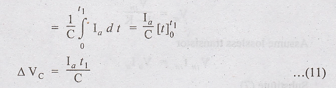
From
Equation (7)
Substitute
t1 in (11)
Advantages
i.
It can step up the output voltage without a transformer
ii.
High efficiency due to single transistor
iii.
Input current is continuous which is very desirable for sources like battery
Disadvantages
1.
Output voltage is very sensitive to variations in the duty cycle K and is
difficult to stabilize the regulator.
2.
It is difficult to protect the output circuit in case of short circuit as the
transistor is connected in shunt with the load.
3.
Requires larger filter capacitor and inductor compared to buck regulator.
4. There is no isolation from input to output
Applications
1.
Hybrid electric vehicles
2.
Lighting systems
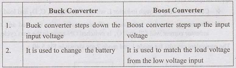
Comparison
of Buck and Boost Converter
Electronic Devices and Circuits: Unit V: Power Amplifiers and DC/DC Converters : Tag: : Circuit Diagram, Equivalent Circuits, Derivations, Advantages, Disadvantages, Applications - Boost Regulator
Related Topics
Related Subjects

Electronic Devices and Circuits
EC3353 - EDC - 3rd Semester - ECE Dept - 2021 Regulation | 3rd Semester ECE Dept 2021 Regulation